Page 91 - 02. Subyek Computer Aided Design - Beginner’s Guide to SOLIDWORKS 2019- Level 1 by Alejandro Reyes
P. 91

Part Modeling


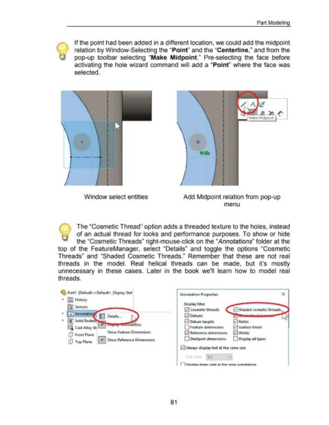
                                                                     If the point had been added in a different location, we could add the midpoint


                                                                     relation by Window-Selecting the "Point" and the "Centerline," and from the


                                                                     pop-up  toolbar  selecting  "Make  Midpoint."  Pre-selecting  the  face  before


                                                                     activating the hole wizard  command will  add a "Point" where the face was


                                                                     selected.


                                                                                                                                                                                    0


                                                                                                                                                                                       - .&&
                                                                     --------


                                                                              Window select entities                                                                    Add Midpoint relation from pop-up


                                                                                                                                                                                                              menu


                                                       ~ The "Cosmetic Thread" option adds a threaded texture to the holes, instead


                                                       \ -::/  of an actual thread for looks and  performance purposes. To show or hide


                                                                       the "Cosmetic Threads" right-mouse-click on the "Annotations" folder at the


                                                      top  of  the  FeatureManager,  select  "Details"  and  toggle  the  options  "Cosmetic


                                                      Threads"  and  "Shaded  Cosmetic  Threads."  Remember  that  these  are  not  real


                                                      threads  in  the  model.  Real  helical  threads  can  be  made,  but  it's  mostly


                                                      unnecessary  in  these  cases.  Later  in  the  book  we'll  learn  how  to  model  real


                                                      threads.


                                                        ~ Part1  (Default<< Default> _Display Stat
                                                                                                                                                                     Annotation Properties                                                                        X
                                                          ._  ~ History


                                                               ~Sensors                                                                                                  Display filter

                                                                                                                                                                          0  Cosmetic threads                         0  Shaded cosmetic threads

                                                          ._  00 Annotatio  1: I Details ...                                                                              0  Datums

                                                          ._  fjj Solid Bodies                                                                                            0  Datum targets                            0  Notes
                                                              o-
                                                              g=; Cast Alloy St• ..._____.                                                                               D Feature dimensions                         0  Surface finish

                                                               ,-;1  F         PI                  Show Feature Dimensions                                                I-./I Reference dimensions                  0Welds
                                                               L.tJ  ront  ane
                                                                                                                                                                         D DimXpert dimensions                        D Display all types
                                                               c!J  Top Plane  0  Show Reference Dimensions
                                                                                         1

                                                                                                                                                                      0  Always display text at the same size


                                                                                                                                                                          Text scale:         1:1


                                                                                                                                                                      n  Di~DiaV itPm~ nnlv in thP VLPW OfLPnta tinn


                                                                                                                                                             81
   86   87   88   89   90   91   92   93   94   95   96