
Page 89 - 02. Subyek Computer Aided Design - Beginner’s Guide to SOLIDWORKS 2019- Level 1 by Alejandro Reyes
P. 89
Part Modeling
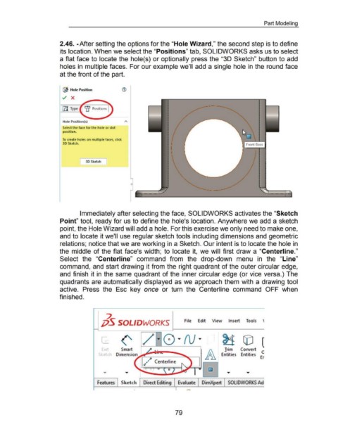
2.46. -After setting the options for the "Hole Wizard," the second step is to define
its location. When we select the "Positions" tab, SOLIDWORKS asks us to select
a flat face to locate the hole( s) or optionally press the "3D Sketch" button to add
holes in multiple faces. For our example we'll add a single hole in the round face
at the front of the part.
'AS.
@ Hole Position ®
Hole Position(s)
Select the face for the hole or slot
position.
•
To create holes on multiple faces, click
•
'
30 Sketch.
t
'
~
[ 30 Sketch ]
0
. -- ~---
Immediately after selecting the face, SOLIDWORKS activates the "Sketch
Point" tool, ready for us to define the hole's location. Anywhere we add a sketch
point, the Hole Wizard will add a hole. For this exercise we only need to make one,
and to locate it we'll use regular sketch tools including dimensions and geometric
relations; notice that we are working in a Sketch. Our intent is to locate the hole in
the middle of the flat face's width; to locate it, we will first draw a "Centerline."
Select the "Centerline" command from the drop-down menu in the "Line"
command, and start drawing it from the right quadrant of the outer circular edge,
and finish it in the same quadrant of the inner circular edge (or vice versa.) The
quadrants are automatically displayed as we approach them with a drawing tool
active. Press the Esc key once or turn the Centerline command OFF when
finished.
7.
;jS SOLIDWORKS File Edit View Insert Tools '
~ G) (
Trim Convert
Entities Entities E~
Features Sketch Direct Editing Evaluate DimXpert SOLIDWORKS Ad
79