
Page 25 - Biaxial Multiaxial Fatigue and Fracture
P. 25
10 K, DANG VAN, A. BIGNONNET AND 1L. FAYARD
The design method was derived from several fatigue tests with corresponding finite element
calculations performed at different loading conditions on stress-relieved elementary welded
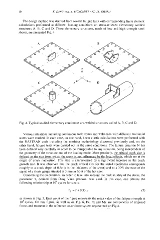
structures A, B, C and D. These elementary structures, made of low and high strength steel
sheets, are presented Fig. 4.
/
Fig. 4. Typical studied elementary continuous arc-welded structures called A, B, C and D.
Various situations including continuous weld zones and weld ends with different multiaxial
states were studied. In each case, on one hand, linear elastic calculations were performed with
the NASTRAN code including the meshing methodology discussed previously and, on the
other hand, fatigue tests were carried out in the same conditions. The failure criterion N has
been defined very carefully in order to be transposable to any situation, being independent of
the geometry of the structure and of the loading mode. More precisely, the critical crack size is
defined as the size from which the crack is not influenced bv the local effects, which are at the
origin of crack nucleation. This size is characterised by a significant increase in the crack
growth rate. It was observed that the crack critical size for the tested specimens corresponds
roughly to a crack depth of 0.5e (e is the thickness of the sheet) and to a 30% decrease of the
signal of a strain gauge situated at 3 mm in front of the hot spot.
Concerning the calculations, in order to take into account the multiaxiality of the stress, the
parameter TO derived from Dang Van's proposal was used. In this case, one obtains the
following relationship at lo6 cycles for steels:
as shown in Fig. 5. Each point of the figure represents the mean value of the fatigue strength at
lo6 cycles. On this figure, as well as on Fig. 6, Fx, Fz and Mz are components of imposed
forces and moment in the reference co-ordinate system represented on Fig.4.