
Page 28 - Biaxial Multiaxial Fatigue and Fracture
P. 28
Asse.~sJnent of Welded Shcctures by a Structural Multiaxial Fatigue Approach 13
Some remarks on the influence of residual stresses
Quantitative analysis of the influence of residual stresses on a welded structure is in general
difficult because the distribution of these stresses depends on different factors like welding
process, thickness of the sheet, but also on the geometry and the boundary conditions (thermal
and mechanical) of the structure. These factors may modify the temperature history, the
rigidity of the thermo-mechanical structure and finally the distribution and the intensity of the
residual stresses. It is well known that residual stresses can have a great influence on the
fatigue behaviour of welded structures made of thick metal sheet. Nevertheless, as it has
already been shown for some automotive body applications, it is most of the time not necessary
to take the residual stresses into account. The main reason is that the welded sheets are thin so
that the temperature gradients through the thickness are not so important as in the thick sheet.
Moreover, the surrounding elements are rather flexible which limits the residual stress level at
relatively <dong range, (compared to the thickness of the sheet and the representative volume
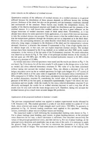
element). However, a structure like element D represented in Fig. 4 has a high rigidity due to
its tubular shape and, in that case, one can expect important residual stresses. The residual
stresses have been measured by the X-ray method, on as welded and after 3000 cycles loaded
component, in the vicinity of the hot spots of the D elementary structure. No stress relaxation
was observed as shown in Fig. 8. The value of the principal residual stresses in the vicinity of
the hot spots are 250 MPa and -50 MPa; the residual hydrostatic tension is 66 MPa which
induces a TO decrease of 22 MPa.
As welded and stress relieved specimens were tested and the results are shown in Fig. 9. On
one hand, Fig. 9 (a) shows for all the tests results N with respect to the design stress TO for both
as welded and stress relieved elementary structures D. The value of q has been calculated
without taking into account the residual stresses. Thus, one obtains a decrease of the TO-N
fatigue resistance curve on the as welded specimens for high cycle fatigue (N 2 lo6 cycles) of
about 25 MPa which is of the same order of magnitude of the measured stress contribution (25
MPa compared to 22 MPa). On the other hand, calculations have been performed on the same
as welded elementary structure D, considering the initial value of the residual hydrostatic
pressure of 66 MPa at the hot spots, as measured experimentally. Figure 9 (b) shows the new
calculation and test results: while the results for the stress relieved elementary structure D are
obviously unchanged, the results for as welded structure increase in such a way that all the
results now fit very well with the mean design curve TO-N. Therefore, taking into account the
residual stresses gives a much more accurate fatigue life prediction.
Application of the proposed methods to Sonsino’s results
The previous computational method was applied to analyse experimental results obtained by
C.M. Sonsino [I21 . The studied specimen is a tube of Icm thick welded on a plate of 2.5 cm
thick, stress relieved and made of high strength steel (yield stress: 520 MPa). Its geometry is
presented in Fig. 10. Several loading conditions were applied to this specimen : bending,
torsion, combined in phase and out of phase torsion and bending.
The numerical model is built following the recommended meshing rules shown in Fig. 3.
For in phase loadings (pure bending, pure torsion, in phase bending-torsion), as the principal
stress directions do not vary, a direct calculation is sufficient. One calculates successively the
values of the principal geometrical stress, and then derives Q. For out of phase loadings, as the
principal stress directions and amplitudes vary at any time of the cycle, it is necessary to apply
the general Dang Van procedure. One has to maximise the parameter d of Eq.(4), that
quantifies the risk of fatigue. The maximum occurs at a definite instant t of the loading cycle.