
Page 362 - Biaxial Multiaxial Fatigue and Fracture
P. 362
346 c. CAL~ R. CITARELLA AND M. PERRELLA
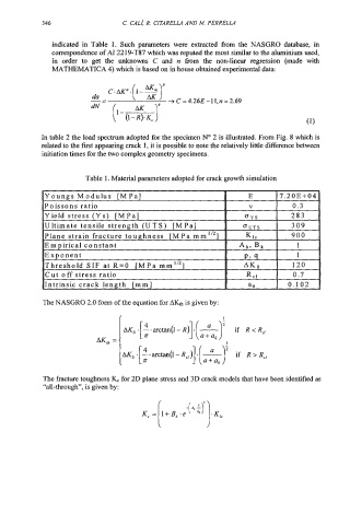
indicated in Table 1. Such parameters were extracted fiom the NASGRO database, in
correspondence of AI 22 19-T87 which was reputed the most similar to the aluminium used,
in order to get the unknowns C and n hm the non-linear regression (made with
MATHEMATICA 4) which is based on in house obtained experimental data:
In table 2 the load spectrum adopted for the specimen No 2 is illustrated. From Fig. 8 which is
related to the first appearing crack 1, it is possible to note the relatively little difference between
initiation times for the two complex geometry specimens.
Table 1. Material parameters adopted for crack growth simulation
Youngs Modulus [MPa] E 7.2OE-tO4
Poissons ratio V 0.3
Yield stress (Y s) [M Pa] - 283 .
, OYS .
Ultimate tensile strength (UTS) [MPa] OUTS 309
Plane strain fracture toughness IMPa mm1’21 K IC 900
E m p iric a1 con st ant Ak, Bk 1
Exponent P- 9 1
‘Threshold SIF at R=O fMPa mm1’21 AKO 120
ICut off stress ratio R rl 1 0.7
IIntrinsic crack length [mm] I a0 1 0.102 I
The NASGRO 2.0 form of the equation for AK& is given by:
if R < R,
if R > R,
The fracture toughness & for 2D plane stress and 3D crack mods that have ,een identified as
“all-through”, is given by:
K, fr4 -e -[ 4;) ’)-&,