
Page 360 - Biaxial Multiaxial Fatigue and Fracture
P. 360
344 c. CAL~, R. CITARELLA AND M. PERRELLA
Complex geometry cracked plates: two- and three-dimensional crack propagation
Two dimensional. For that concern the two-dimensional long crack propagation, a complex
MSD initial scenario was artificially created on a rectangular plate (Fig. 3), by means of
notched holes (a triangular notch was cut in correspondence of each hole) and, after the pre-
cracking process, four different cracks simultaneously propagating were obtained. The
propagating crack lengths were monitored on both sides of the specimen in order to check the
correctness of the load introduction on the specimen: any misalignment between the machine
grips could create a bending condition for the specimen and consequently an elliptical
propagating crack front [4]. This check, together with the strain gauge measurements, allowed
assessing the validity of the 2D hypothesis for such long crack propagation analysis.
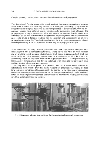
Three dimensional. To study the through the thickness crack propagation a triangular notch
emanating from hole 2 (corresponding to crack 2 in Fig. 3) was cut. After the crack initiation
and pre-cracking period, a quarter elliptical comer crack started to propagate. Such crack was
monitored by an optical measuring system based on a moving camera (Fig. 4), in order to
alternatively follow the two break points of the elliptical crack front. The images obtained by
the (manually) moving camera (Fig. 5) were elaborated by an image analysis software in order
to obtain the two ellipse semi-axes measures.
For long crack initiation period it is possible, with an in house made software, to
automatically make periodic photo that can be recorded and postprocessed, avoiding the need
for a continuous surveillance of the specimen by the operator. In the latter case two camera are
needed for measuring the two semi-axes and only a short propagation length can be monitored
before the crack tip get out of focus (but this drawback can be overcome by using special lenses
or with an automatically moving camera).
Fig. 4. Equipment adopted for monitoring the through the thickness crack propagation.