
Page 389 - Biaxial Multiaxial Fatigue and Fracture
P. 389
The Environment Effect on Fatigue Crack Growth Rates in 7049 Aluminium Alloy at ... 373
FRACTOGRAPHY
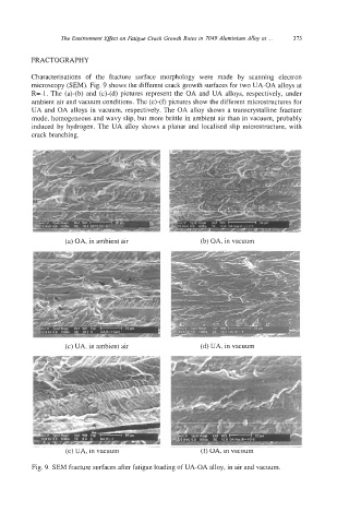
Characterisations of the fracture surface morphology were made by scanning electron
microscopy (SEM). Fig. 9 shows the different crack growth surfaces for two UA-OA alloys at
R=-1. The (a)-(b) and (c)-(d) pictures represent the OA and UA alloys, respectively, under
ambient air and vacuum conditions. The (e)-(f) pictures show the different microstructures for
UA and OA alloys in vacuum, respectively. The OA alloy shows a transcrystalline fracture
mode, homogeneous and wavy slip, but more brittle in ambient air than in vacuum, probably
induced by hydrogen. The UA alloy shows a planar and localised slip microstructure, with
crack branching.
(a) OA, in ambient air (b) OA, in vacuum
a
I
I
(c) UA, in ambient air (d) UA, in vacuum
(e) UA, in vacuum (t) UA, in vacuum
Fig. 9. SEM fracture surfaces after fatigue loading of UA-OA alloy, in air and vacuum.