
Page 429 - Biaxial Multiaxial Fatigue and Fracture
P. 429
Cyclic Behaviour of a Dupler Stainless Steel Under Multiaxial Loading: Experiments and Modelling 413
identified using non-proportional tests. Identification was performed with the software SiDoLo
(optimisation program) developed by Pilvin [30].
The identification of constitutive models is always difficult to carry out and several sets of
material parameters can be found which does not fit too bad the whole experimental series. It is
often difficult to give a physical meaning to these parameters because of the interactions which
can occur between them. The choice of the appropriate set of parameters is then ambiguous.
Proceeding with consistent stages, this difficulty is decreased. The disadvantage of this method
is that optimisation possibilities are restrained.
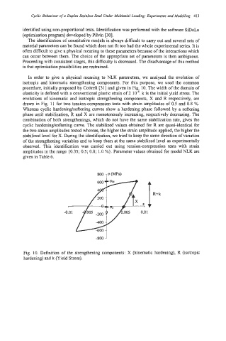
In order to give a physical meaning to NLK parameters, we analysed the evolution of
isotropic and kinematic strengthening components. For this purpose, we used the common
procedure, initially proposed by Cottrell [31] and given in Fig. 10. The width of the domain of
elasticity is defined with a conventional plastic strain of 2 k is the initial yield stress. The
evolutions of kinematic and isotropic strengthening components, X and R respectively, are
drawn in Fig. 11 for two tension-compression tests with strain amplitudes of 0.5 and 0.8 %.
Whereas cyclic hardeninglsoftening curves show a hardening phase followed by a softening
phase until stabilization, R and X are monotonously increasing, respectively decreasing. The
combination of both strengthenings, which do not have the same stabilization rate, gives the
cyclic hardeninglsoftening curve. The stabilized values obtained for R are quasi-identical for
the two strain amplitudes tested whereas, the higher the strain amplitude applied, the higher the
stabilized level for X. During the identification, we tried to keep the same direction of variation
of the strengthening variables and to keep them at the same stabilized level as experimentally
observed. This identification was carried out using tension-compression tests with strain
amplitudes in the range (0.35; 0.5; 0.8; 1.0 %}. Parameter values obtained for model NLK are
given in Table 6.
R+k
7
-0.01 0.01
-800 ’
Fig. 10. Definition of the strengthening components: X (kinematic hardening), R (isotropic
hardening) and k (Yield Stress).