
Page 459 - Biaxial Multiaxial Fatigue and Fracture
P. 459
Microcmck Propagation Under Non-Proportional Multiaxial Alternating Loading 443
Axial loading is built up by the plunger of the servo-hydraulic test machine. The circumferen-
tial strain is generated by a pressure difference of the surrounding media. While the outer pres-
sure is generated by a nitrogen compressor, the inner pressure is built up by a servo-hydraulic
compressor that uses fully demineralised water as pressure medium. During the test, only the
inner pressure is cycled, while the outer pressure is held constant (pa=20 MPa). As a result of
this special layout we are able to perform non-proportional multiaxial fatigue tests under pure
alternating loading. This is different from other experimenters, e.g. Dietmann et. al. [3] who
investigated non-proportional fatigue, too. In cause of their test facility, which uses no outer
pressure, all their experiments were afflicted with positive mean stress and positive minimum
to maximum stress ratio (R-ratio). All experiments are fully strain-controlled.
The specimen
Ascertaining an optimised geometry of the specimen for this special case of loading was not
trivial. It was necessary to find a geometry having a sufficient resistance to instability, but not
too high a stiffness, so that we could achieve sufficient strains. Furthermore, we had to ensure
that the distribution of forces in the measurement area was homogeneous. So, we decided in
favour of a waisted form of the specimen. The real measurement area was a small part in the
middle of the whole specimen only. In this area, smallest wall thickness was encountered.
The first version of our specimens had a linear connection from the measurement zone to
the rest of the specimen. As a result of this geometry chosen we had a preferential crack
initiation at the transition point. FE analyses revealed an obvious stress increasing at this
transition point. With the aid of FE optimisation a new transition geometry was created which
had no stress increasing in the transition point. This was achieved by using a large transition
radius. Unfortunately, this new geometry was susceptible to instability, so that we could not
realise sufficient strain amplitudes. In a third step, we therefore reduced the measurement area
and used a somewhat smaller transition radius to achieve a sufficient stiffness of the specimen,
which was high enough to resist instability. The resulting minimum stress increase at the
transition point as compared to version two, has not yet caused any preferential crack initiation.
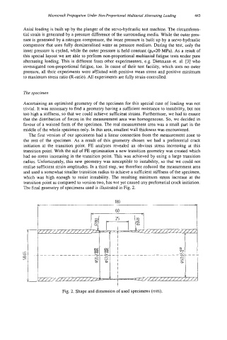
The final geometry of specimens used is illustrated in Fig. 2.
180
I
Fig. 2. Shape and dimension of used specimens (mm).