
Page 462 - Biaxial Multiaxial Fatigue and Fracture
P. 462
446 M. WEICK AND 1 AKTAA
Loading procedure
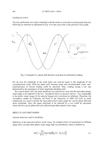
The tests performed were strain-controlled with the strain in axial and circumferential direction
following sin functions as illustrated in Fig. 4 for one cycle with a time period of 10 seconds.
b
Fig. 4. Example for a phase shift between axial and circumferential loading.
For all tests the amplitude of the axial strain was selected equal to the amplitude of the
circumferential strain. With the phase shift between axial and circumferential strain, non-
proportionality of biaxial loading could be specified. Thus, loading during a test was
determined by the parameters of strain amplitude and phase shift.
For a given phase shift, the strain amplitude was selected in a way that the equivalent plastic
strain range to be expected in the test - introduced below in the next section - was comparable
to the plastic strain ranges of the uniaxial fatigue tests considered as reference. Therefore, the
viscoplastic model by Chaboche [4] fitted to the behaviour of AIS1 316 L(N) at room
temperature was used to predict the equivalent plastic strain range for a given phase shift and
strain amplitude. Thus, the strain amplitude to be selected for a test could be calculated
iteratively for a given phase shift and a desired equivalent plastic strain range.
RESULTS AND DISCUSSION
Lifetime behaviour and its modelling
Definition of the equivalent plastic strain range. To compare results of experiments at different
phase shifts, an equivalent plastic strain range A&; was introduced, which is defined as: