
Page 463 - Biaxial Multiaxial Fatigue and Fracture
P. 463
Microcrack Propagation Under Non-Proportional Multiaxial Alternating Loading 447
Here $(t) is the plastic strain tensor at a time t and Ep,(t,,) is the plastic strain tensor at a time
to. To obtain the equivalent plastic strain range, the magnitude (Euclidean norm:
llKll= fi ,/-) of the difference tensor $,(t) - %(to) must be calculated during
=
a cycle for every reading point couple. The maximum magnitude of the difference tensor is
then multiplied by the factor & for reduction to the uniaxial case delivering the equivalent
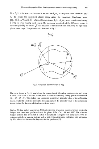
plastic strain range. This procedure is illustrated in Fig. 5.
Fig. 5. Graphical determination of A&:
The curve shown in Fig. 5. results from the connection of all reading points ascertained during
a cycle. This curve is located in the plane of volume constancy during plastic deformation
+ +E: = 0). The dashed line represents an arbitrary absolute value of the differential
tensor, while the solid line represents the maximum of the absolute value of the differential
tensor, just as the diameter of the circumscribing circle.
Fatigue lifetime and its description. Following the test procedure presented above, multiaxial
fatigue tests have been performed with the phase shifts of 45, 90, and 135". The observed
fatigue lifetime data are listed in Table 3 and plotted in Figure 6 in comparison with the
reference data from uniaxial tests as well as tests with proportional multiaxial tests performed
by Windelband on the same facility with similar specimens [SI.