
Page 60 - Biaxial Multiaxial Fatigue and Fracture
P. 60
Multiaxial Fatigue Assessment of Welded Structures by Local Approach 45
The advantage of these approaches is the relatively easy procedure for a design purpose.
However two main drawbacks can be retained. The effective maximum stress existing at the
weld toe is not the referred stress used for the assessment of the weld despite the fact indeed
that this value is the origin of the fatigue damage. The second difficulty consists in the uniaxial
stress states used for evaluating the weld durability. As a matter of fact the notch effect
constraints existing at the weld toe and the possibly multiaxial loading of the structure
generally induce multiaxial stress states. In the case of rotating principal stress directions, a
multiaxial fatigue criterion is the only way to properly account for the effective influence of
such stresses in fatigue.
PRESENTATION OF THE PROPOSED LOCAL APPROACH
This approach is developed for the design of welded structures of all-terrain vehicles. When
such a vehicle is moving on chaotic ground at high speed, its structure and mechanical
components are subjected to vibrations capable of inducing fatigue cracks especially in notched
areas and welded parts. This is the reason why many all-terrain vehicles built all over the world
suffer from progressive cracking. Controlling the fatigue dimensioning of structures under
complex loading becomes thus an essential condition in the design process. Furthermore,
controlling the fatigue strength of welded parts constitutes an important technico-economic
advantage. The aim of this section is to present the approach developed and its application in
order to ascertain fatigue strength under complex loading.
Since the fatigue phenomenon is very local, whereas the phenomenon generating it is
vehicle-wide, the design approach must necessarily be multiscale. The approach developed
results in 3 steps. Starting from the terrain, the first step consists in simulating or testing a
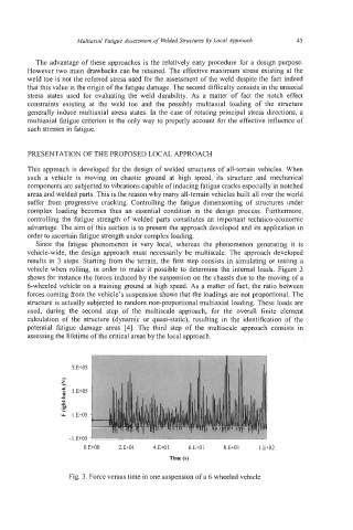
vehicle when rolling, in order to make it possible to determine the internal loads. Figure 3
shows for instance the forces induced by the suspension on the chassis due to the moving of a
6-wheeled vehicle on a training ground at high speed. As a matter of fact, the ratio between
forces coming from the vehicle’s suspension shows that the loadings are not proportional. The
structure is actually subjected to random non-proportional multiaxial loading. These loads are
used, during the second step of the multiscale approach, for the overall finite element
calculation of the structure (dynamic or quasi-static), resulting in the identification of the
potential fatigue damage areas [4]. The third step of the multiscale approach consists in
assessing the lifetime of the critical areas by the local approach.
-1 E+O5 ’
0 E+OO 2 E+O1 4.E+01 6 E+O1 8 E+O1 1 E+02
Time (s)
Fig. 3. Force versus time in one suspension of a 6-wheeled vehicle