
Page 62 - Biaxial Multiaxial Fatigue and Fracture
P. 62
Multiaxial Fatigue Assessment of Welded Structures by Local Approach 47
Stress states histories may present peaks overshooting the material yield stress. The
plasticity resulting from these stress peaks modifies the material stress-strain response because
of stress hardening. Hence, plasticity modifies the damage kinetics. The plastic correction is
made with the hypothesis that the total strain remains constant. The elastic-plastic model
corresponding to the Chaboche non-linear isotropic and kinematic hardening model is used [ 51.
Eqs (3), (4) and (5) describe the yield surface and the kinematic and isotropic stress hardening
rules of this model.
1
3 -
f (a, fi, R) = J('X - k) - R(p) =[-(a - fi) : (x - %)I2 - R(p) = 0 (3)
2
(4)
2
dX = -C, .dEP - C.X.dp (5)
3
where is the deviatoric stress tensor, % and R(p) are the kinematic and isotropic parts of the
stress hardening respectively. R(p) is divided into the initial yield stress & and the isotropic
hardening which maximum value is Q. Q < 0 corresponds to a softening of the material
whereas Q > 0 corresponds to a material hardening.
The multiaxial fatigue criterion used is based over the critical plane concept. Such a
criterion defines a so-called damage indicator related to any material plane (or facet). This
indicator is generally a function of the shear and normal components acting onto this facet. The
principle is to search the most damaged plane, i.e. the critical plane. The assumption is made
that this material plane drives the fatigue behaviour of the material as it is the first plane to
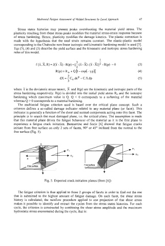
experience a fatigue crack initiation. Bannantine and Socie [6] showed that fatigue cracks
initiate from free surface on only 2 sets of facets, 90" or 45" inclined from the normal to the
free surface (Fig. 5).
Fig. 5. Expected crack initiation planes (from [6])
The fatigue criterion is thus applied to those 2 groups of facets in order to find out the one
that is submitted to the highest amount of fatigue damage. On each facet, the shear stress
history is calculated; the rainflow procedure applied to one projection of that shear stress
makes it possible to identify and extract the cycles from the stress states histories. For each
cycle, the criterion is constructed by combining the shear stress amplitude and the maximum
hydrostatic stress encountered during the cycle, that is: