
Page 244 - Bio Engineering Approaches to Cancer Diagnosis and Treatment
P. 244
9.5 Acoustophoretic motion of particles in a PDMS microchannel using SAW 243
FIGURE 9.12 The fluid flow (acoustic streaming) after applying acoustic field.
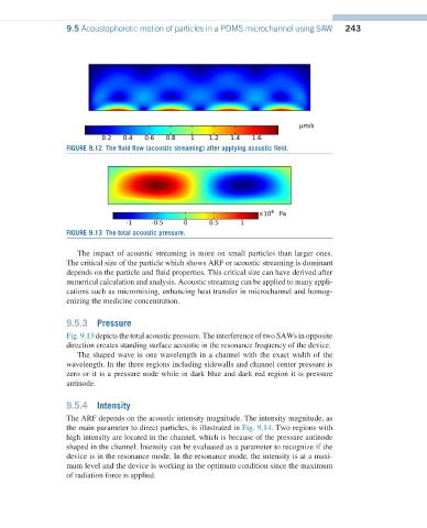
FIGURE 9.13 The total acoustic pressure.
The impact of acoustic streaming is more on small particles than larger ones.
The critical size of the particle which shows ARF or acoustic streaming is dominant
depends on the particle and fluid properties. This critical size can have derived after
numerical calculation and analysis. Acoustic streaming can be applied to many appli-
cations such as micromixing, enhancing heat transfer in microchannel and homog-
enizing the medicine concentration.
9.5.3 Pressure
Fig. 9.13 depicts the total acoustic pressure. The interference of two SAWs in opposite
direction creates standing surface acoustic in the resonance frequency of the device.
The shaped wave is one wavelength in a channel with the exact width of the
wavelength. In the three regions including sidewalls and channel center pressure is
zero or it is a pressure node while in dark blue and dark red region it is pressure
antinode.
9.5.4 Intensity
The ARF depends on the acoustic intensity magnitude. The intensity magnitude, as
the main parameter to direct particles, is illustrated in Fig. 9.14. Two regions with
high intensity are located in the channel, which is because of the pressure antinode
shaped in the channel. Intensity can be evaluated as a parameter to recognize if the
device is in the resonance mode. In the resonance mode, the intensity is at a maxi-
mum level and the device is working in the optimum condition since the maximum
of radiation force is applied.