
Page 279 - Biomass Gasification, Pyrolysis And Torrefaction Practical Design and Theory
P. 279
Chapter | 8 Design of Biomass Gasifiers 255
Biomass
Drying
Pyrolysis
Air Air
Combustion
Gasification
Gas
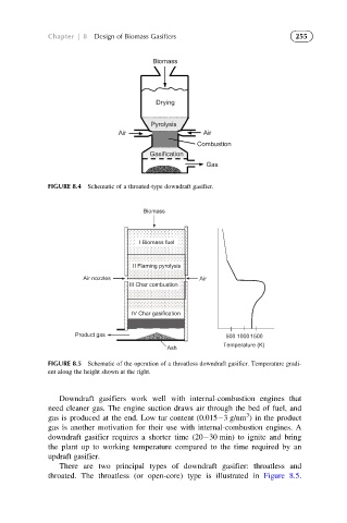
FIGURE 8.4 Schematic of a throated-type downdraft gasifier.
Biomass
I Biomass fuel
II Flaming pyrolysis
Air nozzles Air
III Char combustion
IV Char gasification
Product gas 500 1000 1500
Temperature (K)
Ash
FIGURE 8.5 Schematic of the operation of a throatless downdraft gasifier. Temperature gradi-
ent along the height shown at the right.
Downdraft gasifiers work well with internal-combustion engines that
need cleaner gas. The engine suction draws air through the bed of fuel, and
3
gas is produced at the end. Low tar content (0.015 3 g/nm ) in the product
gas is another motivation for their use with internal-combustion engines. A
downdraft gasifier requires a shorter time (20 30 min) to ignite and bring
the plant up to working temperature compared to the time required by an
updraft gasifier.
There are two principal types of downdraft gasifier: throatless and
throated. The throatless (or open-core) type is illustrated in Figure 8.5.