
Page 281 - Biomass Gasification, Pyrolysis And Torrefaction Practical Design and Theory
P. 281
Chapter | 8 Design of Biomass Gasifiers 257
reactions and temperature distribution along the gasifier height. In one ver-
sion of the throatless downdraft gasifier, the open-core type, the air enters
from the top along with the feed. This type is free from some of the pro-
blems of other downdraft gasifiers.
8.2.2.2 Throated Gasifier
The cross-sectional area of a throated (also called constricted) gasifier is
reduced at the throat and then expanded as shown in Figure 8.4. The purpose
of the constriction is for the oxidation (combustion) zone to be at the narrow-
est part of the throat and to force all of the pyrolysis gas to pass through this
narrow passage. Air is injected through nozzles just above the constriction.
The height of the injection is about one-third of the way up from the bottom
(Reed and Das, 1988, p. 33).
The movement of the entire mass of pyrolysis products through this hot
and narrow zone results in a uniform temperature distribution over the cross-
section and allows most of the tar to crack there. In the 1920s, a French
inventor, Jacques Imbert, developed the original design, which is popularly
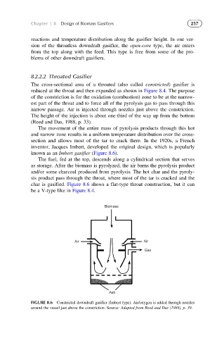
known as an Imbert gasifier (Figure 8.6).
The fuel, fed at the top, descends along a cylindrical section that serves
as storage. After the biomass is pyrolyzed, the air burns the pyrolysis product
and/or some charcoal produced from pyrolysis. The hot char and the pyroly-
sis product pass through the throat, where most of the tar is cracked and the
char is gasified. Figure 8.6 shows a flat-type throat construction, but it can
be a V-type like in Figure 8.4.
Biomass
Air Air
Gas
Ash
FIGURE 8.6 Constricted downdraft gasifier (Imbert type). Air/oxygen is added through nozzles
around the vessel just above the constriction. Source: Adapted from Reed and Das (1988), p. 39.