
Page 287 - Biomass Gasification, Pyrolysis And Torrefaction Practical Design and Theory
P. 287
Chapter | 8 Design of Biomass Gasifiers 263
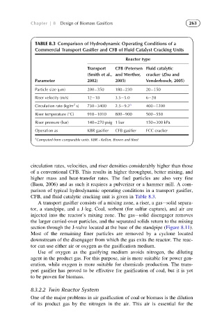
TABLE 8.3 Comparison of Hydrodynamic Operating Conditions of a
Commercial Transport Gasifier and CFB of Fluid Catalyst Cracking Units
Reactor type
Transport CFB (Petersen Fluid catalytic
(Smith et al., and Werther, cracker (Zhu and
Parameter 2002) 2005) Venderbosch, 2005)
Particle size (μm) 200 350 180 230 20 150
Riser velocity (m/s) 12 18 3.5 5.0 6 28
2
Circulation rate (kg/m s) 730 3400 2.5 9.2 a 400 1200
Riser temperature ( C) 910 1010 800 900 500 550
Riser pressure (bar) 140 270 psig 1 bar 150 300 kPa
Operation as KBR gasifier CFB gasifier FCC cracker
a
Computed from comparable units. KBR - Kellon, Brown and Root
circulation rates, velocities, and riser densities considerably higher than those
of a conventional CFB. This results in higher throughput, better mixing, and
higher mass and heat-transfer rates. The fuel particles are also very fine
(Basu, 2006) and as such it requires a pulverizer or a hammer mill. A com-
parison of typical hydrodynamic operating conditions in a transport gasifier,
CFB, and fluid catalytic cracking unit is given in Table 8.3.
A transport gasifier consists of a mixing zone, a riser, a gas solid separa-
tor, a standpipe, and a J-leg. Coal, sorbent (for sulfur capture), and air are
injected into the reactor’s mixing zone. The gas solid disengager removes
the larger carried-over particles, and the separated solids return to the mixing
section through the J-valve located at the base of the standpipe (Figure 8.11).
Most of the remaining finer particles are removed by a cyclone located
downstream of the disengager from which the gas exits the reactor. The reac-
tor can use either air or oxygen as the gasification medium.
Use of oxygen as the gasifying medium avoids nitrogen, the diluting
agent in the product gas. For this purpose, air is more suitable for power gen-
eration, while oxygen is more suitable for chemicals production. The trans-
port gasifier has proved to be effective for gasification of coal, but it is yet
to be proven for biomass.
8.3.2.2 Twin Reactor System
One of the major problems in air gasification of coal or biomass is the dilution
of its product gas by the nitrogen in the air. This air is essential for the