
Page 291 - Biomass Gasification, Pyrolysis And Torrefaction Practical Design and Theory
P. 291
Chapter | 8 Design of Biomass Gasifiers 267
CO 2
Cyclone
CaO Product
CFB/transport gas
regenerator
Bubbling fluidized-
bed gasifier Heat
exchanger
CaCO 3 Fuel Water
Steam Product gas
for application
External heating
of regenerator CO 2 for
sequestration
CO 2
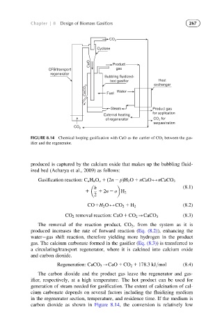
FIGURE 8.14 Chemical looping gasification with CaO as the carrier of CO 2 between the gas-
ifier and the regenerator.
produced is captured by the calcium oxide that makes up the bubbling fluid-
ized bed (Acharya et al., 2009) as follows:
Gasification reaction: C n H h O o 1 ð2n 2 pÞH 2 O 1 nCaO2nCaCO 3
h (8.1)
1 1 2n 2 o H 2
2
CO1H 2 O2CO 2 1 H 2 (8.2)
CO 2 removal reaction: CaO 1 CO 2 -CaCO 3 (8.3)
The removal of the reaction product, CO 2 , from the system as it is
produced increases the rate of forward reaction (Eq. (8.2)), enhancing the
water gas shift reaction, therefore yielding more hydrogen in the product
gas. The calcium carbonate formed in the gasifier (Eq. (8.3)) is transferred to
a circulating/transport regenerator, where it is calcined into calcium oxide
and carbon dioxide.
Regeneration: CaCO 3 -CaO 1 CO 2 1 178:3kJ=mol (8.4)
The carbon dioxide and the product gas leave the regenerator and gas-
ifier, respectively, at a high temperature. The hot product can be used for
generation of steam needed for gasification. The extent of calcination of cal-
cium carbonate depends on several factors including the fluidizing medium
in the regenerator section, temperature, and residence time. If the medium is
carbon dioxide as shown in Figure 8.14, the conversion is relatively low