
Page 290 - Biomass Gasification, Pyrolysis And Torrefaction Practical Design and Theory
P. 290
266 Biomass Gasification, Pyrolysis and Torrefaction
Upflowing Downflowing
chamber chamber
Fluidizing agents
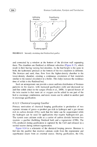
FIGURE 8.13 Internally circulating dual fluidized-bed gasifier.
and connected by a window at the bottom of the division wall separating
them. The chambers are fluidized at different velocities (Figure 8.13), which
result in their having varying bed densities. As the bed height is the same in
both, the hydrostatic pressure at the bottom of the two chambers is different.
The biomass and sand, thus, flow from the higher-density chamber to the
lower-density chamber, creating a continuous circulation of bed materials
similar to the natural circulation in a boiler. This helps increase the residence
time of solids in the fluidized bed.
Such an arrangement can provide a more uniform distribution of biomass
particles in the reactor, with increased gasification yield and decreased tar
and fine solids (char) in the syngas (Freda et al., 2008). A special feature of
the twin reactor is that more air or oxygen can be added in one part of the
bed to encourage combustion, and more steam can be added in another part
to encourage gasification.
8.3.2.3 Chemical Looping Gasifier
Primary motivation of chemical looping gasification is production of two
separate streams of gases—a product gas rich in hydrogen and a gas stream
rich in carbon dioxide (CO 2 ) such that the latter can be sequestrated while
the hydrogen can be used for applications that require hydrogen-rich gas.
The system uses calcium oxide as a carrier of carbon dioxide between two
reactors: a gasifier (bubbling fluidized bed) and a regenerator (CFB). The
CO 2 produced during gasification is captured by the CaO and released in a
second reactor during sorbent regeneration.
Figure 8.14 is a schematic of the chemical looping process. Biomass is
fed into the gasifier that receives calcium oxide from the regenerator and
superheated steam from an external source. During gasification, the CO 2