
Page 294 - Biomass Gasification, Pyrolysis And Torrefaction Practical Design and Theory
P. 294
270 Biomass Gasification, Pyrolysis and Torrefaction
Fuel Gas to pilot burner
Oxygen
Burner
Pressure
water outlet
Cooling screen
Pressure
water inlet
Quench
water
Cooling jacket
Gas outlet
Water
overflow
Granulated slag
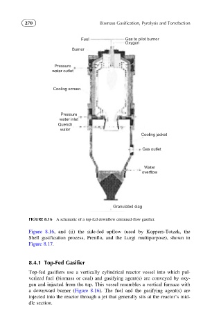
FIGURE 8.16 A schematic of a top-fed downflow entrained-flow gasifier.
Figure 8.16, and (ii) the side-fed upflow (used by Koppers-Totzek, the
Shell gasification process, Prenflo, and the Lurgi multipurpose), shown in
Figure 8.17.
8.4.1 Top-Fed Gasifier
Top-fed gasifiers use a vertically cylindrical reactor vessel into which pul-
verized fuel (biomass or coal) and gasifying agent(s) are conveyed by oxy-
gen and injected from the top. This vessel resembles a vertical furnace with
a downward burner (Figure 8.16). The fuel and the gasifying agent(s) are
injected into the reactor through a jet that generally sits at the reactor’s mid-
dle section.