
Page 295 - Biomass Gasification, Pyrolysis And Torrefaction Practical Design and Theory
P. 295
Chapter | 8 Design of Biomass Gasifiers 271
Syngas to
treating
Hot candle
filter
Fire tube
boiler
Second
stage
Coal
slurry
Char
recycle
First stage
Oxygen
Slag/water
Refractory
slurry
Slag
by-product
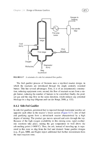
FIGURE 8.17 A schematic of a side-fed entrained-flow gasifier.
The fuel gasifier process of Siemens uses a top-fired reactor design, in
which the reactants are introduced through the single centrally mounted
burner. This has several advantages. First, it is of an axisymmetric construc-
tion, reducing equipment costs; second, the flow of reactant occurs from a sin-
gle burner, reducing the number of burners to be controlled; finally, the prod-
uct gas and the slag flow in the same direction, which reduces any potential
blockage in a slag trap (Higman and van der Burgt, 2008, p. 132).
8.4.2 Side-Fed Gasifier
In side-fed gasifiers, powdered fuel is injected through horizontal nozzles set
opposite each other in the reactor’s lower section (Figure 8.17). Jets of fuel
and gasifying agents form a stirred-tank reactor characterized by a high
degree of mixing. The product gas moves upward and exits through the top.
Because of the high oxygen availability in this mixing zone, rapid exother-
mic reactions take place, raising the gas temperature to well above the
ash-melting point (.1400 C). Thus, the ash, instead of traveling up, is sepa-
rated in this zone as slag from the fuel and drained. Some gasifier designs
(e.g., E-gas, MHI, and Eagle) inject additional fuel further downstream from
the main reaction zone.