Page 31 - Biomedical Engineering and Design Handbook Volume 1, Fundamentals
P. 31

8  BIOMEDICAL SYSTEMS ANALYSIS

                                                             λ 13
                                           1                        3
                                              Gel layer                  GIT
                                                        λ
                                   λ 12                  14
                                         λ 21
                                                                         λ
                                                     λ 41                 43
                               2                λ 42  4
                                  Sol layer             Macrophages
                                                λ 24

                                         λ 52       λ 25  λ 54  λ 45

                                          5  Epithelium                  λ
                                            subep. tissue                 46
                                                   λ 56


                                          6
                                            LN    Blood


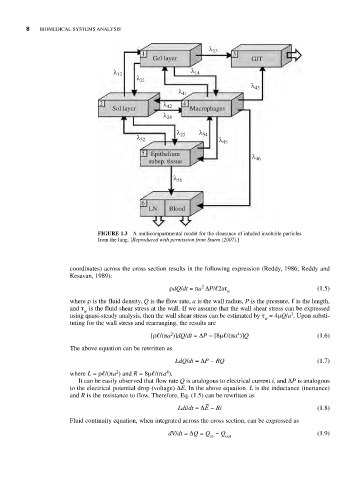
                              FIGURE 1.3  A multicompartmental model for the clearance of inhaled insoluble particles
                              from the lung. [Reproduced with permission from Sturm (2007).]


                       coordinates) across the cross section results in the following expression (Reddy, 1986; Reddy and
                       Kesavan, 1989):
                                                  ρdQ/dt =πa ΔP/ 2aτ                       (1.5)
                                                           2
                                                                  w
                       where ρ is the fluid density, Q is the flow rate, a is the wall radius, P is the pressure,   is the length,
                       and τ is the fluid shear stress at the wall. If we assume that the wall shear stress can be expressed
                           w
                                                                                    3
                       using quasi-steady analysis, then the wall shear stress can be estimated by τ = 4μQ/a . Upon substi-
                                                                             w
                       tuting for the wall stress and rearranging, the results are
                                                                     4
                                                   2
                                             [ρ /(πa )]dQ/dt =ΔP − [8μ /(πa )]Q            (1.6)
                       The above equation can be rewritten as
                                                    LdQ/dt =ΔP − RQ                        (1.7)
                                                 4
                                   2
                       where L =ρ /(πa ) and R = 8μ /(πa ).
                         It can be easily observed that flow rate Q is analogous to electrical current i, and ΔP is analogous
                       to the electrical potential drop (voltage) ΔE. In the above equation. L is the inductance (inertance)
                       and R is the resistance to flow. Therefore, Eq. (1.5) can be rewritten as
                                                            −
                                                     Ldi/dt =ΔE − Ri                       (1.8)
                       Fluid continuity equation, when integrated across the cross section, can be expressed as
                                                  dV/dt =ΔQ = Q − Q                        (1.9)
                                                             in   out
   26   27   28   29   30   31   32   33   34   35   36