
Page 110 - Biomedical Engineering and Design Handbook Volume 2, Applications
P. 110
OVERVIEW OF CARDIOVASCULAR DEVICES 89
The indications for implantation of TAHs and VADs remain similar to those for the IABP, but are
usually reserved for patients who have failed balloon pump support and/or maximal medical therapy.
Since the last edition of this chapter (Gage and Wagner, 2002), some VADs have been approved as
an alternative to transplantation in specific patient populations, a practice otherwise known as “des-
tination therapy” (Rose et al., 2001). VADs approved for destination therapy include the Heartmate
XVE in the United States and the Novacor LVAS within Europe. Current FDA-approved VADs are
placed for postcardiotomy support or as a bridge to either transplantation or recovery (Willman
et al., 1999).
3.8.3 Current Device Design
Intra-Aortic Balloon Pump. The first clinical use of the
intra-aortic balloon pump (IABP) was reported in 1968
(Kantrowitz et al., 1968). Although updated with electronics
and computer control, the basic equipment of the modern
IABP system remains similar to units introduced decades ago.
An IABP system consists of an external pump control console
which monitors physiologic patient variables (electrocardio-
gram and blood pressure) and delivers a bolus of gas to a
catheter-mounted balloon located within the patient’s aorta
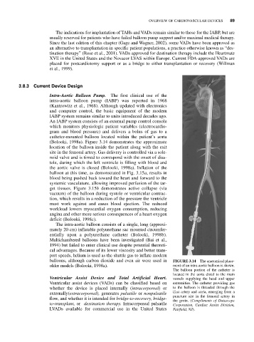
(Bolooki, 1998a). Figure 3.14 demonstrates the approximate
location of the balloon inside the patient along with the exit
site in the femoral artery. Gas delivery is controlled via a sole-
noid valve and is timed to correspond with the onset of dias-
tole, during which the left ventricle is filling with blood and
the aortic valve is closed (Bolooki, 1998a). Inflation of the
balloon at this time, as demonstrated in Fig. 3.15a, results in
blood being pushed back toward the heart and forward to the
systemic vasculature, allowing improved perfusion of the tar-
get tissues. Figure 3.15b demonstrates active collapse (via
vacuum) of the balloon during systole or ventricular contrac-
tion, which results in a reduction of the pressure the ventricle
must work against and eases blood ejection. The reduced
workload lowers myocardial oxygen consumption, reducing
angina and other more serious consequences of a heart oxygen
deficit (Bolooki, 1998c).
The intra-aortic balloon consists of a single, long (approxi-
mately 20 cm) inflatable polyurethane sac mounted circumfer-
entially upon a polyurethane catheter (Bolooki, 1998b).
Multichambered balloons have been investigated (Bai et al.,
1994) but failed to enter clinical use despite potential theoreti-
cal advantages. Because of its lower viscosity and better trans-
port speeds, helium is used as the shuttle gas to inflate modern
balloons, although carbon dioxide and even air were used in FIGURE 3.14 The anatomical place-
older models (Bolooki, 1998a). ment of an intra-aortic balloon is shown.
The balloon portion of the catheter is
located in the aorta distal to the main
Ventricular Assist Device and Total Artificial Heart. vessels supplying the head and upper
Ventricular assist devices (VADs) can be classified based on extremities. The catheter providing gas
whether the device is placed internally (intracorporeal) or to the balloon is threaded through the
externally(extracorporeal), generates pulsatile or nonpulsatile iliac artery and aorta, emerging from a
puncture site in the femoral artery in
flow, and whether it is intended for bridge-to-recovery, bridge- the groin. (Compliments of Datascope
to-transplant, or destination therapy. Intracorporeal pulsatile Corporation, Cardiac Assist Division,
LVADs available for commercial use in the United States Fairfield, NJ).