
Page 142 - Biomedical Engineering and Design Handbook Volume 2, Applications
P. 142
DESIGN OF RESPIRATORY DEVICES 121
To gas analyzer
Pressure transducer
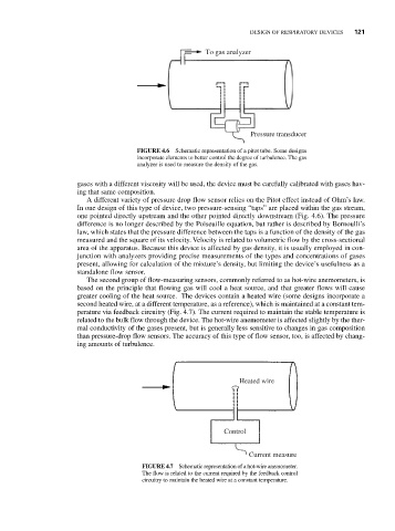
FIGURE 4.6 Schematic representation of a pitot tube. Some designs
incorporate elements to better control the degree of turbulence. The gas
analyzer is used to measure the density of the gas.
gases with a different viscosity will be used, the device must be carefully calibrated with gases hav-
ing that same composition.
A different variety of pressure drop flow sensor relies on the Pitot effect instead of Ohm’s law.
In one design of this type of device, two pressure-sensing “taps” are placed within the gas stream,
one pointed directly upstream and the other pointed directly downstream (Fig. 4.6). The pressure
difference is no longer described by the Poiseuille equation, but rather is described by Bernoulli’s
law, which states that the pressure difference between the taps is a function of the density of the gas
measured and the square of its velocity. Velocity is related to volumetric flow by the cross-sectional
area of the apparatus. Because this device is affected by gas density, it is usually employed in con-
junction with analyzers providing precise measurements of the types and concentrations of gases
present, allowing for calculation of the mixture’s density, but limiting the device’s usefulness as a
standalone flow sensor.
The second group of flow-measuring sensors, commonly referred to as hot-wire anemometers, is
based on the principle that flowing gas will cool a heat source, and that greater flows will cause
greater cooling of the heat source. The devices contain a heated wire (some designs incorporate a
second heated wire, at a different temperature, as a reference), which is maintained at a constant tem-
perature via feedback circuitry (Fig. 4.7). The current required to maintain the stable temperature is
related to the bulk flow through the device. The hot-wire anemometer is affected slightly by the ther-
mal conductivity of the gases present, but is generally less sensitive to changes in gas composition
than pressure-drop flow sensors. The accuracy of this type of flow sensor, too, is affected by chang-
ing amounts of turbulence.
Heated wire
Control
Current measure
FIGURE 4.7 Schematic representation of a hot-wire anemometer.
The flow is related to the current required by the feedback control
circuitry to maintain the heated wire at a constant temperature.