
Page 154 - Biomedical Engineering and Design Handbook Volume 2, Applications
P. 154
DESIGN OF RESPIRATORY DEVICES 133
3 2 1.0
Mouth pressure (cmH 2 O/L/s) –1 1 0 A Flow (L/s) 0.0 B
0.5
–2
–3 –0.5
–1.0
0 1 2 3 4 5 6 7 0 1 2 3 4 5 6 7
Time (s) Time (s)
C
D
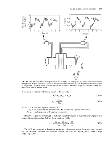
FIGURE 4.19 Diagram of the airflow perturbation device (APD). The rotating disk (C) creates changes in resistance
through which the patient breathes. The ratio of delta pressure (A) to delta flow (B) with the partial obstructions is equal
to the patient’s airways resistance. The side opening (D) provides a flow outlet for periods when the rotating disk
obstructs the outlet of the flow sensor.
When there is a partial obstruction, airflow is described by
P A = V obs ( R resp + R obs ) (4.18)
P m obs,
R obs = (4.19)
V obs
where V obs = flow with a partial obstruction
R obs = resistance of the flow sensor and the device with a partial obstruction
P = mouth pressure with a partial obstruction
m,obs
If the wheel spins rapidly enough so that each partial obstruction is short, the alveolar pressure is
assumed to remain constant. Solving these equations yields
P m obs − P m open, Δ P
,
R resp = = (4.20)
V open − V obs −Δ V
The APD has been used to determine respiratory resistance of people from very young to very
old, and the results demonstrate the decline of resistance with child age as growth makes airways
larger (Fig. 4.20).