
Page 152 - Biomedical Engineering and Design Handbook Volume 2, Applications
P. 152
DESIGN OF RESPIRATORY DEVICES 131
P b
P m
Shutter
P b
P
Flow m
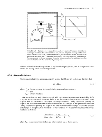
FIGURE 4.17 Illustration of a body plethysmograph, or body box. The patient sits within the
sealed rigid-walled box. For measurements of lung volumes, the patient pants against the closed
shutter while box pressure (P ) and mouth pressure (P ) are recorded as shown. The slope of the
b m
relationship between P and P determines the volume of gas being compressed within the lung.
b m
For measurements of airways resistance, the shutter is then opened and an additional recording
is made, this time with flow rather than P on the y axis.
m
multiple determinations of lung volume. It requires the large rigid box, one or two pressure trans-
ducers, and usually a flow sensor or spirometer.
4.5.4 Airways Resistance
Measurements of airways resistance generally assume that Ohm’s law applies and therefore that
P A = VR aw (4.14)
where P = alveolar pressure (measured relative to atmospheric pressure)
A
V = flow
R = airways resistance
aw
One method uses a body plethysmograph with a pneumotachograph at the mouth (Fig. 4.17).
It repeats the measurements described above in the discussion of lung volumes and adds a series
of pants with the mouthpiece valve open, allowing for airflow. During open-valve panting, the
slope of the relationship between airflow at the mouth and changes in box pressure is recorded.
During closed-valve panting, the slope of the relationship between changes in alveolar pressure
and changes in box pressure is recorded. The ratio of these two measurements yields the airways
resistance as follows:
Closed valve PP P A
/ Box
A
= = = a R w (4.15)
w
Open valve VP V
/ Box
where P is pressure within the box and other symbols are as shown above.
Box