
Page 153 - Biomedical Engineering and Design Handbook Volume 2, Applications
P. 153
132 MEDICAL DEVICE DESIGN
4.5.5 Respiratory Resistance
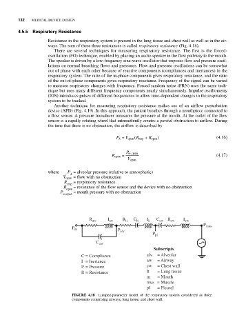
Resistance in the respiratory system is present in the lung tissue and chest wall as well as in the air-
ways. The sum of these three resistances is called respiratory resistance (Fig. 4.18).
There are several techniques for measuring respiratory resistance. The first is the forced-
oscillation (FO) technique, enabled by placing an audio speaker in the flow pathway to the mouth.
The speaker is driven by a low-frequency sine-wave oscillator that imposes flow and pressure oscil-
lations on normal breathing flows and pressures. Flow and pressure oscillations can be somewhat
out of phase with each other because of reactive components (compliances and inertances) in the
respiratory system. The ratio of the in-phase components gives respiratory resistance, and the ratio
of the out-of-phase components gives respiratory reactance. Frequency of the signal can be varied
to measure respiratory changes with frequency. Forced random noise (FRN) uses the same tech-
nique but uses many different frequency components nearly simultaneously. Impulse oscillometry
(IOS) introduces pulses of different frequencies to allow time-dependent changes in the respiratory
system to be tracked.
Another technique for measuring respiratory resistance makes use of an airflow perturbation
device (APD) (Fig. 4.19). In this approach, the patient breathes through a mouthpiece connected to
a flow sensor. A pressure transducer measures the pressure at the mouth. At the outlet of the flow
sensor is a rapidly rotating wheel that intermittently creates a partial obstruction to airflow. During
the time that there is no obstruction, the airflow is described by
P A = V open ( R resp + R open ) (4.16)
P m open,
R open = (4.17)
V open
where P = alveolar pressure (relative to atmospheric)
A
V open = flow with no obstruction
R = respiratory resistance
resp
R = resistance of the flow sensor and the device with no obstruction
open
P = mouth pressure with no obstruction
m,open
R aw I aw R lt C lt I lt C cw R cw I cw
P mus
P m P
alv
P pl
C aw
Subscripts
C = Compliance alv = Alveolar
I = Inertance aw = Airway
P = Pressure cw = Chest wall
R = Resistance lt = Lung tissue
m = Mouth
mus = Muscle
pl = Pleural
FIGURE 4.18 Lumped-parameter model of the respiratory system considered as three
components comprising airways, lung tissue, and chest wall.