
Page 261 - Biomedical Engineering and Design Handbook Volume 2, Applications
P. 261
240 DIAGNOSTIC EQUIPMENT DESIGN
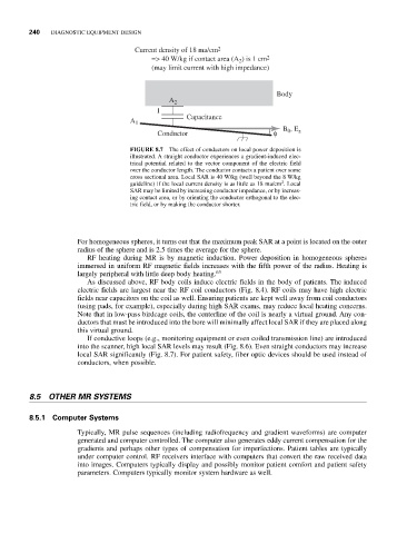
Current density of 18 ma/cm 2
=> 40 W/kg if contact area (A ) is 1 cm 2
2
(may limit current with high impedance)
Body
A 2
I
Capacitance
A 1
Conductor φ B 0 , E z
FIGURE 8.7 The effect of conductors on local power deposition is
illustrated. A straight conductor experiences a gradient-induced elec-
trical potential related to the vector component of the electric field
over the conductor length. The conductor contacts a patient over some
cross sectional area. Local SAR is 40 W/kg (well beyond the 8 W/kg
2
guideline) if the local current density is as little as 18 ma/cm . Local
SAR may be limited by increasing conductor impedance, or by increas-
ing contact area, or by orienting the conductor orthogonal to the elec-
tric field, or by making the conductor shorter.
For homogeneous spheres, it turns out that the maximum peak SAR at a point is located on the outer
radius of the sphere and is 2.5 times the average for the sphere.
RF heating during MR is by magnetic induction. Power deposition in homogeneous spheres
immersed in uniform RF magnetic fields increases with the fifth power of the radius. Heating is
largely peripheral with little deep body heating. 63
As discussed above, RF body coils induce electric fields in the body of patients. The induced
electric fields are largest near the RF coil conductors (Fig. 8.4). RF coils may have high electric
fields near capacitors on the coil as well. Ensuring patients are kept well away from coil conductors
(using pads, for example), especially during high SAR exams, may reduce local heating concerns.
Note that in low-pass birdcage coils, the centerline of the coil is nearly a virtual ground. Any con-
ductors that must be introduced into the bore will minimally affect local SAR if they are placed along
this virtual ground.
If conductive loops (e.g., monitoring equipment or even coiled transmission line) are introduced
into the scanner, high local SAR levels may result (Fig. 8.6). Even straight conductors may increase
local SAR significantly (Fig. 8.7). For patient safety, fiber optic devices should be used instead of
conductors, when possible.
8.5 OTHER MR SYSTEMS
8.5.1 Computer Systems
Typically, MR pulse sequences (including radiofrequency and gradient waveforms) are computer
generated and computer controlled. The computer also generates eddy current compensation for the
gradients and perhaps other types of compensation for imperfections. Patient tables are typically
under computer control. RF receivers interface with computers that convert the raw received data
into images. Computers typically display and possibly monitor patient comfort and patient safety
parameters. Computers typically monitor system hardware as well.