
Page 258 - Biomedical Engineering and Design Handbook Volume 2, Applications
P. 258
DESIGN OF MAGNETIC RESONANCE SYSTEMS 237
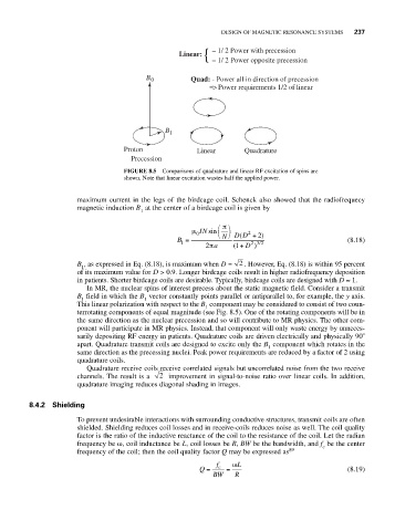
Linear: { – 1/ 2 Power with precession
– 1/ 2 Power opposite precession
B 0 Quad: - Power all in direction of precession
=> Power requirements 1/2 of linear
B 1
Proton Linear Quadrature
Precession
FIGURE 8.5 Comparisons of quadrature and linear RF excitation of spins are
shown. Note that linear excitation wastes half the applied power.
maximum current in the legs of the birdcage coil. Schenck also showed that the radiofrequecy
magnetic induction B at the center of a birdcage coil is given by
1
⎛ π ⎞
μ 0 IN sin ⎝ N ⎠ DD +( 2 2)
B = (8.18)
1
23 2 /
2π a ( 1+ D )
B , as expressed in Eq. (8.18), is maximum when D = 2 . However, Eq. (8.18) is within 95 percent
1
of its maximum value for D > 0.9. Longer birdcage coils result in higher radiofrequency deposition
in patients. Shorter birdcage coils are desirable. Typically, birdcage coils are designed with D ≈ 1.
In MR, the nuclear spins of interest precess about the static magnetic field. Consider a transmit
B field in which the B vector constantly points parallel or antiparallel to, for example, the y axis.
1 1
This linear polarization with respect to the B component may be considered to consist of two coun-
1
terrotating components of equal magnitude (see Fig. 8.5). One of the rotating components will be in
the same direction as the nuclear precession and so will contribute to MR physics. The other com-
ponent will participate in MR physics. Instead, that component will only waste energy by unneces-
sarily depositing RF energy in patients. Quadrature coils are driven electrically and physically 90
apart. Quadrature transmit coils are designed to excite only the B component which rotates in the
1
same direction as the precessing nuclei. Peak power requirements are reduced by a factor of 2 using
quadrature coils.
Quadrature receive coils receive correlated signals but uncorrelated noise from the two receive
channels. The result is a 2 improvement in signal-to-noise ratio over linear coils. In addition,
quadrature imaging reduces diagonal shading in images.
8.4.2 Shielding
To prevent undesirable interactions with surrounding conductive structures, transmit coils are often
shielded. Shielding reduces coil losses and in receive-coils reduces noise as well. The coil quality
factor is the ratio of the inductive reactance of the coil to the resistance of the coil. Let the radian
frequency be ω, coil inductance be L, coil losses be R, BW be the bandwidth, and f be the center
c
frequency of the coil; then the coil quality factor Q may be expressed as 89
f ω L
Q = c = (8.19)
BW R