
Page 333 - Biomedical Engineering and Design Handbook Volume 2, Applications
P. 333
THE PRINCIPLES OF X-RAY COMPUTED TOMOGRAPHY 311
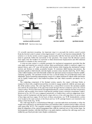
FIGURE 10.55 Specimen rotary stage.
(3) versatile specimen mounting. An important step is to uncouple the motion control system
from the thermal control system so that requirements (1) and (2) can function independently. The
solution is to let the motion system engage mechanically with the thermal system but allow the
latter to passively follow the movement of the specimen. This means that the thermal system
must apply only the weakest of constraint to three-dimensional displacement and offer minimal
resistance to rotation in the vertical axis.
A cone-on-cone contact is a suitable geometry for mechanical engagement, provided that the
cone angle and material are correctly chosen. Since good thermal contact is required, copper is a
natural choice, and a 10° cone will provide solid location while keeping the mechanical contact
stiction and friction to within acceptable bounds. To minimize shaft bearing inaccuracies, the
specimen spindle is built directly onto the highly accurate rotary encoder shaft (Fig. 10.55). Here,
a thin-walled stainless steel tube thermally isolates the specimen mount receptacle from the spindle-
clamping assembly. The specimen mount also has a conical surface for good thermal contact and
alignment. Typical mounting arrangements consist of a copper platform to which stable specimens
can be lightly bonded and a thin-walled beryllium tube into which unstable specimens can be
inserted.
The contacting component of the thermal system, namely, the copper cold-stage block, is
required to float with a small downward force in order to engage positively with the specimen spin-
dle of the motion system. The cold-stage block has a conical bore to receive the specimen spindle
and controls the temperature of the specimen mount through thermal conduction across the conical
contact surface. Primary heat transfer through thermoelectric coolers maintains the base temperature
variation, and secondary heat transfer from buried cartridge heaters maintains temperature control.
Solutions to Eq. (10.122) were computed numerically to confirm that a uniform temperature distri-
bution could be maintained with the specific shape and size of the cold-stage block for given values
of heat input and heat output. On the basis of these calculations, two 70-W thermoelectric coolers
were located at the outer surfaces of the block and four 16-W cartridge heaters were inserted in one
surface of the block (Fig. 10.56).
The cold-stage block is counterbalanced through a sprocket-and-chain mechanism to offset the
weight and is attached to an unrestrained three-axis miniature slide to permit motion within a 40-mm
cubic space (Fig. 10.57). The complete assembly is supported on a micrometer-adjustable pitch/roll
plate for alignment of the conical engagement bore with the rotational axis of the motion stage. An
environmental chamber, with thin beryllium x-ray path windows, encloses the cold stage and a con-
trolled dry gas bleed prevents water droplet condensation.