
Page 331 - Biomedical Engineering and Design Handbook Volume 2, Applications
P. 331
THE PRINCIPLES OF X-RAY COMPUTED TOMOGRAPHY 309
vertical servo-drive
accuracy 0.1 m
CCD
camera
lateral servo-drive
axial servo-drive accuracy 0.1 m
accuracy 1 m
FIGURE 10.49 Servo-controlled camera traverse. FIGURE 10.50 Motion systems PC interface racks.
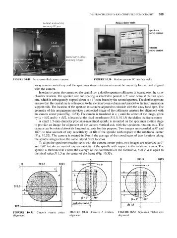
x-ray source central ray and the specimen stage rotation axis must be correctly located and aligned
with the camera.
In order to center the camera on the central ray, a double-aperture collimator is located over the x-ray
chamber window. The aperture size and spacing is selected to provide a 2° cone beam at the first aper-
ture, which is subsequently stopped down to a 1° cone beam by the second aperture. The double aperture
ensures that the central ray is orthogonal to the electron beam column and parallel to the instrumentation
support rails. The location of the aperture axis can be adjusted to coincide with the x-ray focal spot. The
geometry of this arrangement provides a projected image of the collimator aperture for alignment with
the camera center point (Fig. 10.51). The camera is translated in x, z until the center of the image, given
by (a + b)/2 and (c + d)/2, is located at the pixel coordinates (511.5, 511.5) that define the frame center.
A small 1.5-mm-diameter precision-machined spindle is mounted on the specimen motion stage
to provide an image for alignment of the camera vertical axis with the specimen rotation axis. The
camera can be rotated about its longitudinal axis for this purpose. Two images are recorded, at 0° and
180°, to take account of any eccentricity, or tilt of the spindle with respect to the rotational center
(Fig. 10.52). The camera is rotated in q until the average of the coordinates of two locations along
the spindle images have the same lateral pixel location.
To align the specimen rotation axis with the camera center point, two images are recorded at 0°
and 180° to take account of any eccentricity of the spindle with respect to the rotational center. The
spindle is translated in x until the average of the coordinates of the location a, b or c, d is equal to
the pixel value 511.5 at the center of the frame (Fig. 10.53).
FIGURE 10.51 Camera center point FIGURE 10.52 Camera q rotation FIGURE 10.53 Specimen rotation axis
alignment. alignment. alignment.