
Page 326 - Biomedical Engineering and Design Handbook Volume 2, Applications
P. 326
304 DIAGNOSTIC EQUIPMENT DESIGN
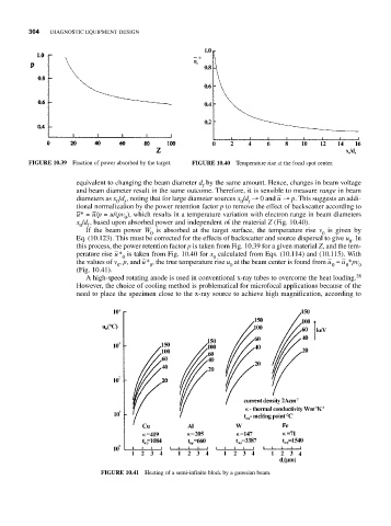
FIGURE 10.39 Fraction of power absorbed by the target. FIGURE 10.40 Temperature rise at the focal spot center.
equivalent to changing the beam diameter d by the same amount. Hence, changes in beam voltage
f
and beam diameter result in the same outcome. Therefore, it is sensible to measure range in beam
–
diameters as x /d , noting that for large diameter sources x /d → 0 and u → p. This suggests an addi-
0
0
f
f
tional normalization by the power retention factor p to remove the effect of backscatter according to
– –
u* = u/p = u/(pv ), which results in a temperature variation with electron range in beam diameters
0
x /d f , based upon absorbed power and independent of the material Z (Fig. 10.40).
0
If the beam power W is absorbed at the target surface, the temperature rise v is given by
0
0
Eq. (10.123). This must be corrected for the effects of backscatter and source dispersal to give u . In
0
this process, the power retention factor p is taken from Fig. 10.39 for a given material Z, and the tem-
–
perature rise u* is taken from Fig. 10.40 for x calculated from Eqs. (10.114) and (10.115). With
0
0
–
–
–
the values of v , p, and u* , the true temperature rise u at the beam center is found from u = u *pv 0
0
0
0
0
0
(Fig. 10.41).
A high-speed rotating anode is used in conventional x-ray tubes to overcome the heat loading. 28
However, the choice of cooling method is problematical for microfocal applications because of the
need to place the specimen close to the x-ray source to achieve high magnification, according to
FIGURE 10.41 Heating of a semi-infinite block by a gaussian beam.