
Page 322 - Biomedical Engineering and Design Handbook Volume 2, Applications
P. 322
300 DIAGNOSTIC EQUIPMENT DESIGN
Solving for the M [s] by successively subtracting series for M [ks]/k, with k chosen to eliminate
n n
progressively higher terms in M [ks], gives the expression
n
π ⎡ 1 1 1 1 1 ⎤
M [] = M() + M( σ ) − M( σ ) + M( σ ) + B Mk ( σ ... (10.109)
σ
σ
)
7
5
3
n ⎢ r r r r k r ⎥
4 ⎣ 3 5 7 k ⎦
where k takes on the odd values 1, 3, 5, etc., and B is 1, 0, or −1 according to
k
m k −1
−
1
B =−() () if r = m
1
k
2
B = 0 if r < m
k
Here, m is the total number of primes into which k can be factored and r is the number of different prime
factors in k. According to Eq. (10.109) the modulation transfer function can be evaluated in terms of the
measured modulation, or contrast values M(s) . However, since a value of M(0) = 1 from Eq. (10.108)
r r
gives a corresponding value M [s] = 0.9538 from Eq. (10.109), we must apply a normalizing factor of
n
1.0484 to the calculated result. We note that the values of M are compounded according to the product
n
of the individual MTFs of the imaging components. For the simple x-ray source and detector combina-
s
D
D
s
tion, we have M = M M , where M is the x-ray source MTF and M is the detector MTF. If the detec-
n n n n n
tor is a film emulsion, the MTF for the digital scanning device should be included in the product.
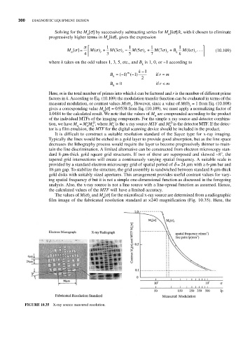
It is difficult to construct a suitable resolution standard of the Sayce type for x-ray imaging.
Typically the lines would be etched in a gold layer to provide good absorption, but as the line space
decreases the lithography process would require the layer to become progressively thinner to main-
tain the line discrimination. A limited alternative can be constructed from electron microscopy stan-
dard 8-mm-thick gold square grid structures. If two of these are superposed and skewed ~8°, the
tapered grid intersections will create a continuously varying spatial frequency. A suitable scale is
provided by a standard electron microscopy grid of spatial period of d = 24 mm with a 6-mm bar and
18-mm gap. To stabilize the structure, the grid assembly is sandwiched between standard 8-mm-thick
gold disks with suitably sized apertures. This arrangement provides useful contrast values for vary-
ing spatial frequency s but it is not a simple one-dimensional function as discussed in the foregoing
analysis. Also, the x-ray source is not a line source with a line-spread function as assumed. Hence,
the calculated values of the MTF will have a limited accuracy.
The values of M(s) and M [s] for the microfocal x-ray source are determined from a radiographic
r n
film image of the fabricated resolution standard at ×240 magnification (Fig. 10.35). Here, the
FIGURE 10.35 X-ray source measured resolution.