Page 317 - Biomedical Engineering and Design Handbook Volume 2, Applications
P. 317

THE PRINCIPLES OF X-RAY COMPUTED TOMOGRAPHY  295


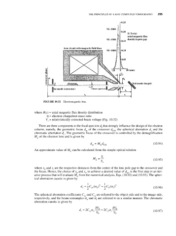
                               FIGURE 10.32  Electromagnetic lens.


                          where B(z) = axial magnetic flux density distribution
                                 h = electron charge/rest-mass ratio
                                V = relativistically corrected beam voltage (Fig. 10.32)
                                 r
                            There are three components to the focal spot size d that strongly influence the design of the electron
                                                               f
                          column, namely, the geometric focus d of the crossover d , the spherical aberration d and the
                                                       m             CO                    s
                          chromatic aberration d . The geometric focus of the crossover is controlled by the demagnification
                                          c
                          M of the electron lens and is given by
                           L
                                                         d =  M d                           (10.94)
                                                          m
                                                               L CO
                          An approximate value of M can be calculated from the simple optical relation
                                              L
                                                               S
                                                          M ≈   i                           (10.95)
                                                            L
                                                               S o
                          where s and s are the respective distances from the center of the lens pole gap to the crossover and
                               0    i
                          the focus. Hence, the choice of s and s , to achieve a desired value of d , is the first step in an iter-
                                                 0    i                       m
                          ative process that will evaluate M from the numerical analysis, Eqs. (10.92) and (10.93). The spher-
                                                  L
                          ical aberration caustic is given by
                                                       1      3  1     3
                                                                     α
                                                    d =  C (α 0 )  =  C ( )                 (10.96)
                                                     s
                                                                   si
                                                                      i
                                                          so
                                                       2         2
                          The spherical aberration coefficients C and C are referred to the object side and to the image side,
                                                     so    si
                          respectively, and the beam semiangles a and a are referred to in a similar manner. The chromatic
                                                       o    i
                          aberration caustic is given by
                                                            δ V      δ V
                                                   d = 2 C α  0  = 2 C α  0                 (10.97)
                                                                   ci i
                                                        co o
                                                    c
                                                            V 0       V 0
   312   313   314   315   316   317   318   319   320   321   322