
Page 330 - Biomedical Engineering and Design Handbook Volume 2, Applications
P. 330
308 DIAGNOSTIC EQUIPMENT DESIGN
10.4.4 Motion Systems
The specimen motion required for cone-beam reconstruction is a lateral axes (x, z) translation and a
vertical axis b rotation. The scanning cycle needs to be under computer control in order to synchro-
nize mechanical movement with data acquisition. Further, the control must provide a level of accu-
racy that, at the very least, matches the measured resolution of the x-ray source. In practice, an
encoded accuracy in lateral translation of 10,000 counts per mm and a rotational accuracy of 2000
counts per degree of revolution can be achieved with commercial components.
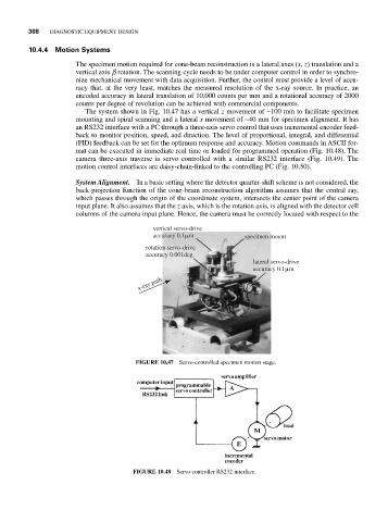
The system shown in Fig. 10.47 has a vertical z movement of ~100 mm to facilitate specimen
mounting and spiral scanning and a lateral x movement of ~40 mm for specimen alignment. It has
an RS232 interface with a PC through a three-axis servo control that uses incremental encoder feed-
back to monitor position, speed, and direction. The level of proportional, integral, and differential
(PID) feedback can be set for the optimum response and accuracy. Motion commands in ASCII for-
mat can be executed in immediate real time or loaded for programmed operation (Fig. 10.48). The
camera three-axis traverse is servo controlled with a similar RS232 interface (Fig. 10.49). The
motion control interfaces are daisy-chain-linked to the controlling PC (Fig. 10.50).
System Alignment. In a basic setting where the detector quarter-shift scheme is not considered, the
back-projection function of the cone-beam reconstruction algorithm assumes that the central ray,
which passes through the origin of the coordinate system, intersects the center point of the camera
input plane. It also assumes that the z axis, which is the rotation axis, is aligned with the detector cell
columns of the camera input plane. Hence, the camera must be correctly located with respect to the
vertical servo-drive
accuracy 0.1 m specimen mount
rotation servo-drive
accuracy 0.001deg
lateral servo-drive
accuracy 0.1 m
x-ray path
FIGURE 10.47 Servo-controlled specimen motion stage.
FIGURE 10.48 Servo controller RS232 interface.