
Page 329 - Biomedical Engineering and Design Handbook Volume 2, Applications
P. 329
THE PRINCIPLES OF X-RAY COMPUTED TOMOGRAPHY 307
FIGURE 10.45 80-mm intensifier/demagnifier CCD digital x-ray camera.
small in size, ~7 mm × 7 mm. Also, this device is principally sensitive to light and not to x-rays. Hence,
the x-ray photons must be down shifted in frequency at the input plane and the image must be reduced
to match the CCD. If the image demagnification m is provided by a simple lens system, with an f-number
2
f/#, the light-gathering power will be 1/(f/#) . Therefore, f/# needs to be kept as small as possible
which can be achieved by a reduction in m. If a demagnifying intensifier is used, then a portion of the
demagnification is provided without loss (Fig. 10.45). Furthermore, if the photon conversion scintilla-
tor is coated directly onto the intensifier, rather than onto a conventional fiber-optic faceplate, additional
losses are avoided. The aim is to provide as high a detective quantum efficiency (DQE) as possible,
2
where DQE = (snr/SNR) and snr, SNR are the signal-to-noise ratios at input and output, respectively. 31
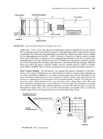
Phase Contrast Imaging. In conventional x-ray imaging, the contrast is dependent on the photo-
electric and Compton scattering processes with sensitivity to density variations Δr/r, depending on
the relative absorption of adjacent rays. In phase contrast imaging, the contrast is dependent on the
elastic Thompson scattering process with sensitivity to density variation Δr/r determined by the
refraction of adjacent rays at the boundaries of the structured density variation. The differences in
refraction create a slight deviation in the x-ray wavefront so that a phase delay occurs. The small
phase differences are separated in a crystal analyzer to form the image. The advantage over absorp-
tion contrast is that the phase delay remains significant even when the detail becomes very small. To
distinguish the phase delay, the x-rays must be monochromatic and parallel. With a sufficiently
coherent source this can be achieved with crystal monochromator (Fig. 10.46).
FIGURE 10.46 Phase contrast imaging.