
Page 379 - Biomedical Engineering and Design Handbook Volume 2, Applications
P. 379
BREAST IMAGING SYSTEMS: DESIGN CHALLENGES FOR ENGINEERS 357
modalities acquire volumetric rather than planar image data, permitting thin slices of image data to
be extracted and viewed individually without superposition of structure from other anatomy outside
that slice. X-ray tomosynthesis, whether applied to imaging the breast or other parts of the anatomy,
uses multiple views obtained over a range of viewing angles to produce a 3D image. Unlike x-ray
CT in which views are obtained over 240 to 360°, a range sufficient to form a mathematically
complete projection data set for 3D image reconstruction, the angular range in tomosynthesis is
much less, typically 40 to 50°. Tomosynthesis has evolved out of x-ray tomography, which has been
practiced since the early 1900s. Early tomographic imaging was performed by linear translation of
the x-ray tube and screen-film cassette in opposite directions on either side of the patient. This has
the effect of blurring out the images of structures outside of a plane passing through the ful-
crum of the tube-receptor motion. The availability within the past decade of large area digital detec-
tors capable of rapid readout has given birth to digital tomosynthesis, in which a series of low-dose
digital images is obtained, permitting reconstruction of an arbitrary number of image planes via dig-
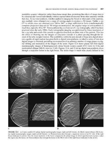
ital shifting and summation of the images of the series. Figure 12.4 shows planar full field digital
mammography images of heterogeneously dense breasts (cranio-caudal (CC) views in 12.4a and
mediolateral oblique (MLO) views in 12.4b). Figures 12.4c and 12.4d are digital tomosynthesis slices
through a suspicious lesion in the right breast. The lesion shape is much more clearly defined in the
A B
C D
FIGURE 12.4 (a) Cranio-caudal (CC) planar digital mammography images (right and left breasts). (b) Medio-lateral oblique (MLO) pla-
nar digital mammography images (right and left breasts). (c) Tomosynthesis slice through a suspicious lesion in the CC view of the right
breast (indicated by arrow). Note the clearer depiction of the lesion compared to the planar image in which superimposed structures clutter
the region near the lesion. (d) Tomosynthesis slice through the lesion in the MLO view of the right breast (indicated by the arrow).