
Page 93 - Biomedical Engineering and Design Handbook Volume 2, Applications
P. 93
72 MEDICAL DEVICE DESIGN
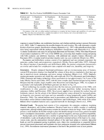
TABLE 3.1 The Five-Position NASPE/BPEG Generic Pacemaker Code
Positions and I. Chamber(s) II. Chamber(s) III. Pacemaker IV. Rate V. Multisite
description paced sensed response modulation pacing
Atrium Atrium Triggered Rate Modulation Atrium
Ventricle Ventricle Inhibited NOne Ventricle
Dual Dual Dual Dual
NOne NOne NOne NOne
The purpose of the code is to allow medical practitioners to recognize the basic features and capabilities of a given pace-
maker. The code alone does not provide a complete description of device features, but is clear and simple to use.
Source: Adapted from Bernstein et al. (2002).
response to sensed rhythms, rate modulation functions, and whether multisite pacing is present (Bernstein
et al., 2002). Table 3.1 summarizes the possible features for each location. The code represents a simpli-
fication of previous generic classification schemes (Bernstein et al., 1987) with antitachyarrythmia func-
tions being represented with the analogous defibrillator classification code (Bernstein et al., 1993).
A similar classification code exists for pacing leads (Bernstein and Parsonnet, 1996a). More than 60 percent
of pacemakers implanted in 1997 were of the DDDR type, possessing dual chamber sensing and pacing
with both excitatory and inhibitory functions, with additional rate adaptive features (Bernstein and
Parsonnet, 2001). A similar trend toward dual chamber units was seen worldwide (Mond et al., 2004).
Pacemaker and defibrillator systems consist of two implanted and one external component: the
generator, cardiac leads, and programmer, respectively (Morley-Davies and Cobbe, 1997). Although
the clinical function of pacemakers and defibrillators differ, the desired component characteristics
are similar and include low complication rates coupled with small size, durability, and longevity.
Generators. Despite enhanced functional performance and an ever-increasing array of features,
current ICD generators displace less than half the volume of those devices implanted a short time ago
due to improved circuit, packaging, and power storage technology (Morris et al., 1999). Similarly,
modern pacemaker generators are small, thin, and weigh only 20 to 30 g (Kusumoto and Goldschlager,
1996). Generator and battery technology allows pacemakers to last approximately 5 to 9 years in the
body (Morley-Davies and Cobbe, 1997), with the more complex dual chamber designs having shorter
lifespans than the simpler, single chamber units (Kusumoto and Goldschlager, 1996). An example of
a pacemaker and implantable defibrillator generator are shown in Fig. 3.8.
Power technology has steadily improved since the first mercury acid batteries of the 1960s, with
modifications in other generator components and usage algorithms further increasing battery
endurance (Jeffrey and Parsonnet, 1998). Novel power supplies have included the nuclear slug and
biokinetic sources, but the advent of the lithiurn-based power source allowed for increased genera-
tor longevity over mercury acid types and was amenable to being hermetically sealed (Jeffrey and
Parsonnet, 1998). The current batteries used in pacemakers and defibrillators differ in formulation.
Pacemakers utilize lithium-iodine batteries (Kusumoto and Goldschlager, 1996) while ICDs utilize
lithium-silver-vanadium batteries and a capacitor network for discharges (Morris et al., 1999).
Electrical Leads. The pacing lead consists of five components: the connector, conductor, insulating
material, electrode(s), and fixation mechanism. Electrical leads have to fulfill a number of conflicting
requirements, although reliable performance remains the dominant criteria (de Voogt, 1999). Leads should
possess a small diameter, be flexible enough to place but durable enough to resist wear, possess favorable
power consumption characteristics, anchor in place to prevent migration, and enjoy good biocompatibility.
Pacing leads can be subdivided into a number of groups based on the area of placement and method
of stimulation. Leads can be placed either on the epicardium (external surface) of the heart or, by a trans-
venous route, onto the endocardium (internal surface) of the right heart atrium or ventricle. Epicardial
leads are used for permanent pacing in pediatric cases, where size considerations or congenital defects
prevent transvenous placement, and in patients who have undergone tricuspid valve replacement (Mitrani
et al., 1999). Percutaneous transvenous placement of the lead is the preferred route in most patients.