
Page 95 - Biomedical Engineering and Design Handbook Volume 2, Applications
P. 95
74 MEDICAL DEVICE DESIGN
To avoid the incompatibilities in mating technologies that arise from having a large number of
electrophysiology (EP) device manufacturers, internationally accepted standards have been developed
to define the mating connection between pacemakers and leads, thus allowing leads from one manu-
facturer to be mated to the generator of another. Originally developed by the British Standards
Institution as the IS-1 specification for low-profile connectors for implantable pacemakers, the stan-
dard has been revised and re-released in 2000 as the ISO 5841-3 standard from the International
Standards Organization as part of their publications governing the design of cardiac pacemakers.
A similar standard (DF-1) exists for ICD shock leads (Morris et al., 1999).
A number of materials have been used for insulation in cardiac pacing leads, including polyethylene,
polysiloxanes, polyurethanes, and poly(ethylene-co-tetrafluoroethylene) (ETFE). Polyethylene was the
original lead insulation material but poor long-term performance has eliminated its use in the pacing lead
market (Crossley, 2000). Polysiloxanes are used in modern electrophysiology leads but have undergone
an evolution in performance and formulation over the years, A limited resistance to tearing required
a relatively thick layer until newer, high-performance polysiloxanes were released (Crossley, 2000).
Polyurethanes possess a high tear strength and, in contrast to early polysiloxane formulas, a low coeffi-
cient of friction, both of which served to popularize polyurethane use; leads could be made smaller and
possessed improved placement characteristics, especially in multiple-lead applications (Schmidt and
Stotts, 1998; Crossley, 2000). The newest coradial bipolar leads utilize a thin layer of ethylene tetrafluo-
roethylene (ETFE) as an insulation coating for the interior, helically wound leads, with a redundant layer
of exterior polyurethane insulation (Schmidt and Stotts, 1998; Crossley, 2000). The coradial leads are
small and appear to have a reduced complication rate compared to coaxial designs (Tyers et al., 1997).
To prevent migration, lead tips are fitted with either passive or active fixation mechanisms.
Passive devices use hooks or tines to secure the line into place, while active fixation methods rely
upon a screw like tip to burrow the lead into the heart tissue. Although active fixation leads have been
considered less likely to dislodge or suffer from complications than passive leads, few major studies
have been performed and some doubt that differences in performance exist in the hands of an expe-
riened implanter (Mitrani et al., 1999). Some situations do warrant active fixation leads, however.
Congenital heart disease may require lead placement in an odd area, which can make active fixation
useful (Mitrani et al., 1999). In the United States, active fixation leads appear to be preferred for
atrial placement, while passive fixation leads are the overwhelming choice when leads are placed in
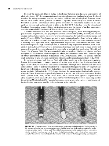
the ventricle (Mond et al., 2004). Figure 3.9 provides a close-up view of a variety of lead tips, reveal-
ing the fixation equipment used for both passive and active methods.
FIGURE 3.9 Close-up views of three pacemaker and/or cardioverter-defibrillator leads. The lead on the far
left is an active fixation lead with a retractable screw embedded in the lead tip. It can be extended after implan-
tation to attach the lead to the heart wall. The middle lead possesses a soluble cap that dissolves within a few
minutes inside the body to reveal a hook or screw for tip fixation. A tined passive fixation lead is shown on
the right. The soft tines become lodged in the irregular inside surface of the heart, preventing lead migration.