
Page 94 - Biomedical Engineering and Design Handbook Volume 2, Applications
P. 94
OVERVIEW OF CARDIOVASCULAR DEVICES 73
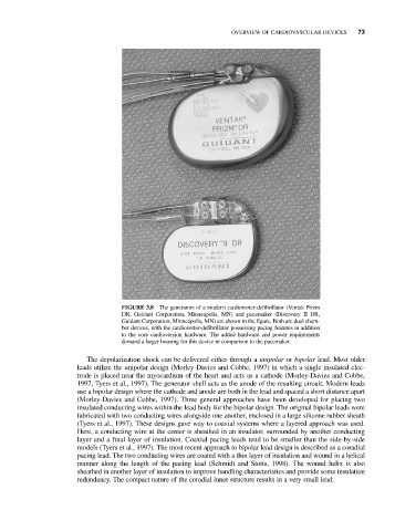
FIGURE 3.8 The generators of a modern cardioverter-defibrillator (Ventak Prizm
DR, Guidant Corporation, Minneapolis, MN) and pacemaker (Discovery II DR,
Guidant Corporation, Minneapolis, MN) are shown in the figure. Both are dual cham-
ber devices, with the cardioverter-defibrillator possessing pacing features in addition
to the core cardioversion hardware. The added hardware and power requirements
demand a larger housing for this device in comparison to the pacemaker.
The depolarization shock can be delivered either through a unipolar or bipolar lead. Most older
leads utilize the unipolar design (Morley-Davies and Cobbe, 1997) in which a single insulated elec-
trode is placed near the myocardium of the heart and acts as a cathode (Morley-Davies and Cobbe,
1997; Tyers et al., 1997). The generator shell acts as the anode of the resulting circuit. Modern leads
use a bipolar design where the cathode and anode are both in the lead and spaced a short distance apart
(Morley-Davies and Cobbe, 1997). Three general approaches have been developed for placing two
insulated conducting wires within the lead body for the bipolar design. The original bipolar leads were
fabricated with two conducting wires alongside one another, enclosed in a large silicone rubber sheath
(Tyers et al., 1997). These designs gave way to coaxial systems where a layered approach was used.
Here, a conducting wire at the center is sheathed in an insulator, surrounded by another conducting
layer and a final layer of insulation. Coaxial pacing leads tend to be smaller than the side-by-side
models (Tyers et al., 1997). The most recent approach to bipolar lead design is described as a coradial
pacing lead. The two conducting wires are coated with a thin layer of insulation and wound in a helical
manner along the length of the pacing lead (Schmidt and Stotts, 1998). The wound helix is also
sheathed in another layer of insulation to improve handling characteristics and provide some insulation
redundancy. The compact nature of the coradial inner structure results in a very small lead.