
Page 86 - Biosystems Engineering
P. 86
Biosystems Analysis and Optimization 67
2.5 Feedback Controller Design
2.5.1 Feedback Control Structure
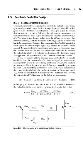
The most commonly used method to control the output of a dynamic
system is by introducing a feedback loop. Figure 2.20 is a block dia-
gram of such a feedback control system. The output y(t) of the system
that we want to control is fed back through sensor measurement H
with measurement noise v(t) to be compared with the reference value
r(t). The latter is the desired value, thus the difference between this
reference value r(t) and the measured output y (t), called the error e(t),
m
has to be minimized. To reach this goal, controller C will translate the
error signal e(t) into an input signal u(t) applied to system G under
control. Because the loop between input and output is closed, this feed-
back controller is also known as a closed-loop controller. In practice,
the output signal y(t) will not only be determined by the input signal
u(t) applied to the system G but is also subject to disturbances w(t).
So that we may be able to design a good controller C, we should
be able to describe the transfer of a reference signal r(t) into the out-
put signal y(t) using the closed-loop controlled system, the tracking
performance. For this purpose, we define the closed-loop transfer
function G (s), describing the transfer from the Laplace transform of
c
the reference signal R(s) to the Laplace transform of the output signal
Y(s). When the effect of the disturbances v(t) is not taken into account,
the output signal Y(s) is given by the following expression:
Y s() = Gs U s () = Gs C s E s () = Gs C s R s () − H(ssY s)( )] (2.80)
()
() ()[
() ()
By bringing all terms in Y(s) to the left, and all transfer functions to
the right, the closed-loop transfer function G (s) can be derived as
c
Ys() Gs C s() Gs C(()s
()
()
Gs() = = = (2.81)
c + 1 +
()
()
()
Rs() 1 Gs C s H s() Ls
W(s)
R(s) + E(s) U(s) ++ Y(s)
C(s) G(s)
–
Y (s) +
m
H(s)
+
V(s)
FIGURE 2.20 Block diagram of a feedback-controlled system.