
Page 158 - Boiler_Operators_Handbook,_Second_Edition
P. 158
Special Systems 143
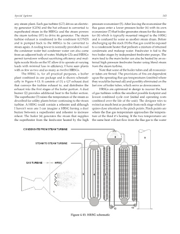
any steam plant. Each gas turbine (GT) drives an electric- pressure economizer (5). After leaving the economizer the
ity generator (GEN) and the hot exhaust is converted to flue gases enter a lower pressure boiler (6) with its own
superheated steam in the HRSGs and the steam powers economizer (7) that boiler generates steam for the deaera-
the steam turbine (ST) to drive its generator. The steam tor (8) which is typically mounted integral to the HRSG
turbine exhaust is condensed in the condenser (COND) and is confused by some as another steam drum. Before
and is pumped back to the HRSGs to be converted to discharging up the stack (9) the flue gas could be exposed
steam again. A cooling tower is normally provided to cool to a condensate heater that preheats a mixture of returned
the condenser water but condenser water can also come condensate and makeup water. Feedwater is fed to the
from an adjacent body of water. Multiple GTs and HRSGs two boiler stages by independent feedwater pumps. The
permit turndown without sacrificing efficiency and mul- main feed to the main boiler can also be heated by an ex-
tiple nozzle blocks on the ST allow it to operate at varying ternal high pressure feedwater heater using bleed steam
loads with minimal loss in efficiency. I have seen plants from the steam turbine.
with as few as two and as many as twelve HRSGs. Note that some of the boiler tubes and all economiz-
The HRSG is, for all practical purposes, a boiler er tubes are finned. The provisions of fins are dependent
plant combined in one package and is shown schemati- upon the operating flue gas temperatures (omitted where
cally in Figure 4-13. It consists of (1) a GT exhaust duct they would be burned off) and possibly eliminated on the
that conveys the turbine exhaust to, and distributes the last row of boiler tubes, which serve as downcomers.
exhaust into the first stages of the boiler portion. A duct HRSGs are optimized in design to recover the heat
burner (2) provides additional heat to the boiler section. of gas turbines within the smallest possible footprint and
The superheater (3) raises the temperature of the steam as lowest combined cycle cost (initial and operating costs
described for utility plants before continuing to the steam combined over the life of the unit). The designer tries to
turbine. A HRSG could contain a reheater and although extract as much heat as possible from each stage which re-
I haven’t seen one I can imagine a HRSG having a duct quires close attention to the pinch points. Pinch points are
burner between a superheater and reheater to increase where the flue gas temperature approaches the tempera-
reheat. The boiler (4) generates the steam that supplies ture of the fluid it’s heating. If the two temperatures are
the superheater from the feedwater heated by the high the same heat will not flow from the flue gas to the water
Figure 4-13. HRSG schematic