
Page 157 - Boiler_Operators_Handbook,_Second_Edition
P. 157
142 Boiler Operator’s Handbook
(4-5) pressure remains about the same and velocity and place two electrodes under water each within an inverted
temperature increase. Mass flow also increases a small test tube of water and force a direct current of electricity
amount due to the addition of the fuel. Air to fuel ratios through the water. Hydrogen is generated at one elec-
are considerably higher than those in a boiler because trode and oxygen at the other and those gases collect in
all the heat from combustion is retained in the flue gases the bottom of the inverted test tubes because the electric-
and more air is required to absorb the heat and keep the ity breaks down the H2O into its two components. The
temperature from exceeding the tolerances of the metal fuel cell combines oxygen in the air and hydrogen in the
of construction. I’m familiar with turbines that run 400% fuel to generate electricity, a reverse of electrolysis.
excess air but more modern designs continue to reduce
that value to reduce the energy used in the compressor
for higher GT efficiency. In the turbine (5-6) pressure HRSGs AND COMBINED CYCLE PLANTS
and temperature drop as the gases convert energy to
the turbine blades to rotate the shaft. Velocity increases HRSGs are connected to the discharge of a gas tur-
as the gases expand through the turbine stages. A GT bine. It’s not uncommon for people to use that abbrevia-
turbine only has reaction blading (see steam turbine tion when discussing simple waste heat boilers. The typi-
descriptions) because there are no nozzles. Finally, at cal HRSG captures the heat remaining in the exhaust of
the outlet of the GT (6-7) an evase (gradual expansion of a gas turbine generator and supplies superheated steam
ductwork) serves to convert some of the velocity pres- to feed a steam turbine also connected to a generator and
sure to static pressure. That allows for a slightly higher that is the typical combined cycle plant. A typical com-
differential pressure across the turbine and the turbine bined cycle plant consists of gas turbine driven electric
outlet pressure reading to be lower than atmospheric for generators with a HRSG at the exhaust of each and steam
turbines without heat recovery and lower than the inlet from the HRSG powering a steam turbine. The steam
pressure to heat recovery equipment. cycle isn’t quite the same as a typical utility plant like
A process used to boost power output of GT gen- the one shown in Figure 1-8 because the combined cycle
erators when summer electrical loads are high is misting. plant is typically a number of HRSGs supplying one or
Immediately after the turbine inlet filters spray nozzles two steam turbine generators.
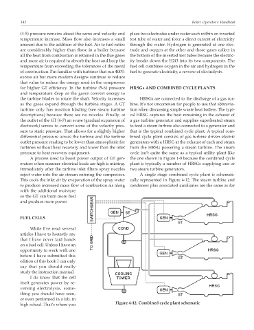
inject water into the air stream entering the compressor. A single stage combined cycle plant is schemati-
This cools the inlet air by evaporation of the spray water cally represented in Figure 4-12. The steam turbine and
to produce increased mass flow of combustion air along condenser plus associated auxiliaries are the same as for
with the additional moisture
so the GT can burn more fuel
and produce more power.
FUEL CELLS
While I’ve read several
articles I have to honestly say
that I have never laid hands
on a fuel cell. Unless I have an
opportunity to work with one
before I have submitted this
edition of this book I can only
say that you should really
study the instruction manual.
I do know that the cell
itself generates power by re-
versing electrolysis, some-
thing you should have seen,
or even performed in a lab, in
Figure 4-12. Combined cycle plant schematic
high school. That’s where you