
Page 202 - Boiler_Operators_Handbook,_Second_Edition
P. 202
Refrigeration & AC 187
Heating Coil conditions at the outlet of the cooling coil to the appa-
Some apparatus, but not all, will have a heating ratus outlet conditions, after the heating coil. A typical
coil after the cooling coil. When cooling of the air isn’t heating application is shown in Figure 5-45.
required heating may be and the coil is there to heat the
supply air leaving the apparatus. It becomes necessary Humidifier
in many installations because of the large, required, Whenever a considerable amount of outdoor air is
quantity of ventilating air adds so much cold outside used for ventilation it has to be heated when the outside
air that heating it is necessary. Even systems with reheat air is cold and, because the heating increases the dry
coils (heating coils in the ductwork supplying different bulb temperature (as indicated by a horizontal line from
portions of the air conditioned space) will have a heat- left to right on the psychrometric chart) the humidity of
ing coil in the main apparatus because the cold air in that air drops. Unless moisture is added to the air the
the ductwork would promote condensation that could personnel in the conditioned space will experience elec-
damage the insulation and ductwork. The clue here is tric shocks and other unpleasant conditions. Humid-
don’t shut down that heating coil in the winter, nor ig- ifiers add moisture to the air and, depending on their
nore it’s lack of operation, thinking the reheat coils will source of water, can also heat or cool the air.
take care of things because wet and falling ceiling tiles The typical home humidifier consists of a high
could be the last thing you remember of that particular pressure spray that atomizes water to form fine droplets
facility. Heating can be performed with electric heating of it and inject them into the air stream coming off the
coils (very expensive to operate), steam or hot water heater. Others use a ceramic or fiber wick that’s soaked
heating coils, or a gas or oil fired furnace. Of course the with water and exposed to the air stream. Some of the
furnace is not a heating coil but it accomplishes the same heat in the air is used to evaporate the water. Being a
purpose and furnaces are discussed later. boiler operator you know how much heat it takes to con-
When there is a heating coil it can be used for par- vert liquid water to a gas so you can see how the line on
tial reheat or simply heating. The apparatus can be op- a psychrometric chart for that service would be drawn
erated for humidity control of the conditioned space by from the conditions at the outlet of the heating coil up
cooling the air more than necessary for temperature con- and to the left, both adding moisture to the air and cool-
trol, in order to remove more moisture from the air, and ing it some.
reheat it to provide the desired supply air temperature. Larger applications can use similar means of hu-
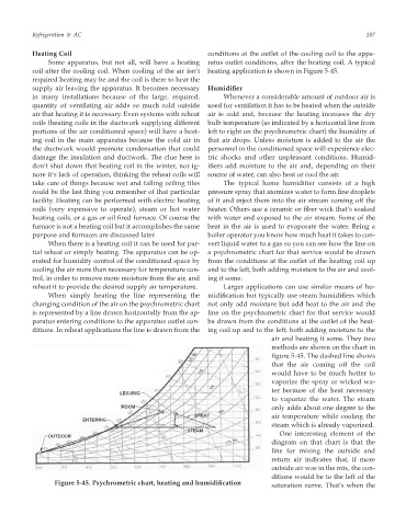
When simply heating the line representing the midification but typically use steam humidifiers which
changing condition of the air on the psychrometric chart not only add moisture but add heat to the air and the
is represented by a line drawn horizontally from the ap- line on the psychrometric chart for that service would
paratus entering conditions to the apparatus outlet con- be drawn from the conditions at the outlet of the heat-
ditions. In reheat applications the line is drawn from the ing coil up and to the left, both adding moisture to the
air and heating it some. They two
methods are shown on the chart in
figure 5-45. The dashed line shows
that the air coming off the coil
would have to be much hotter to
vaporize the spray or wicked wa-
ter because of the heat necessary
to vaporize the water. The steam
only adds about one degree to the
air temperature while cooling the
steam which is already vaporized.
One interesting element of the
diagram on that chart is that the
line for mixing the outside and
return air indicates that, if more
outside air was in the mix, the con-
ditions would be to the left of the
Figure 5-45. Psychrometric chart, heating and humidification
saturation curve. That’s when the