
Page 200 - Boiler_Operators_Handbook,_Second_Edition
P. 200
Refrigeration & AC 185
Blockage of the pan or drain piping by condensate con-
taminated with dust or other debris is a common prob-
lem with air conditioning equipment. Elimination of
the condensate can also be a concern; in hospitals, simi-
lar medical facilities, and production plants the drain is
piped to a sanitary sewer for obvious reasons. In some
cases the drain piping can’t slope down to discharge
into the sewer or a suitable discharge point so small
sumps and pumps are provided to lift the condensate
into a suitable discharge area. The drains should be ar-
ranged in a manner that prevents sewer gases or other
contamination from leaking into the air conditioning
system and the normal solution for that is a ‘P’ trap
like you find under a lavatory sink. A good remedy for
those plugging up is to give them a fresh water rinse
once a year. Regardless they should be checked quar-
terly to ensure water isn’t flooding the drain pan.
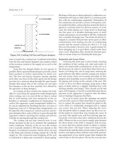
Figure 5-43. Cooling Coil Face and bypass dampers
tures to match the cooling load. Combined with reheat Inspection and Access Doors
coils the face and bypass dampers also permit control Checking the drain pan would include checking
of the moisture content of the supply air as well as the the condition of the cooling coil, inlet and outlet, to
temperature. detect any undesirable accumulations on the coil or in
Note that the damper blades do not operate in the drain pan. In order to check them there has to be a
parallel. These opposed blade dampers provide a more means of looking into, and in large units, entering the
linear position to airflow relationship for better con- space between the filters and the cooling coil. Inspec-
trol. The face and bypass dampers operate opposite tion and access doors are normally provided for this
each other, one closes as the other opens and the design purpose and, hopefully, access to them isn’t blocked by
provides for a pressure drop through the open bypass the piping and wiring on the outside of the unit. The
damper that equals that of the cooling coil and open covers or doors for these openings range from a thin
face dampers so the air flow quantity isn’t altered by piece of sheet metal to a rugged, insulated door with
the operation of these dampers. latching handles and hinges. They should not be left
In constant air flow systems two means are avail- open, half hanging, or loosely mounted because the air
able for controlling the equipment outlet temperature pressure in the apparatus is negative after the filters
when cooling, one is to cool all the air then to reheat and air leaking in bypasses the filters.
the air with heating coils (not necessarily in the air If, as in so many cases, the openings are simply
handler) to maintain conditioned air temperature. To covered with a piece of sheet metal then it’s good prac-
control the apparatus outlet temperature chilled wa- tice to replace the gasket that should be glued to the
ter can be regulated by throttling the flow of water or cover when it’s accidentally damaged and to replace
bypassing some of it. Refrigeration temperatures can any screws that get lost. When replacing the cover
be adjusted with compressor controls and face and by- care should be taken to simply draw up the cover un-
pass dampers allow some of the air to pass through the til the gasket is seated then stop turning the screw. If
apparatus without contacting the cooling coil and mix you don’t the metal cover will bow leaving gaps be-
with the air passing through the cooling coil. tween the screw holes that allow unfiltered air into the
The cooling coil not only removes heat, it con- AHU. Whenever the cover screws simply spin, because
denses moisture in the air to produce the equipment the sheet metal of the AHU is stripped, look for larg-
outlet conditions. Velocity of the air over the cooling er screws that have plastic knobs on them to replace
coil is typically limited to 500 feet per minute so the those old screws. The larger screws will engage in the
droplets of condensed moisture drizzle down the fins stripped holes and the plastic knobs make it possible to
to the drain pan instead of being carried off with the remove and replace them without tools while prevent-
supply air. The condensed water dripping off the coils ing application of too much torque that stripped the
is collected in a drain pan connected to drain piping. screw holes in the first place. Oh, by the way, get new