
Page 195 - Boiler_Operators_Handbook,_Second_Edition
P. 195
180 Boiler Operator’s Handbook
increases the load on the unit. The first function of the tem will draw outside air from a location that is unlike-
condenser is to remove the superheat in the gas, reduc- ly to be contaminated but you will still encounter some
ing its temperature to the corresponding 123°F satura- today that were designed when everyone thought the
tion temperature near (R). Then the refrigerant remains atmosphere was a giant sink that could absorb any-
at the saturation temperature as it is condensed until all thing and remain fresh and clean. Be aware of potential
the gas is converted to liquid near (S). Once all the gas is problems with contaminated outside air and be pre-
converted to liquid the refrigerant is subcooled until it’s pared to do something about it, even if it’s the poor,
about 105°F at the inlet of the capillary. As the pressure but essential, act of entering a regular comment about
drops from the 100 psig in the condenser to 35 psig in it in a log book.
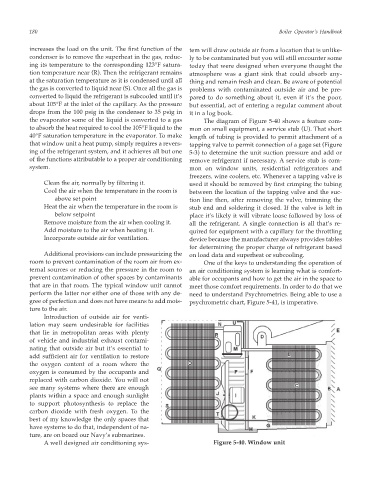
the evaporator some of the liquid is converted to a gas The diagram of Figure 5-40 shows a feature com-
to absorb the heat required to cool the 105°F liquid to the mon on small equipment, a service stub (U). That short
40°F saturation temperature in the evaporator. To make length of tubing is provided to permit attachment of a
that window unit a heat pump, simply requires a revers- tapping valve to permit connection of a gage set (Figure
ing of the refrigerant system, and it achieves all but one 5-3) to determine the unit suction pressure and add or
of the functions attributable to a proper air conditioning remove refrigerant if necessary. A service stub is com-
system. mon on window units, residential refrigerators and
freezers, wine coolers, etc. Whenever a tapping valve is
Clean the air, normally by filtering it. used it should be removed by first crimping the tubing
Cool the air when the temperature in the room is between the location of the tapping valve and the suc-
above set point tion line then, after removing the valve, trimming the
Heat the air when the temperature in the room is stub end and soldering it closed. If the valve is left in
below setpoint place it’s likely it will vibrate loose followed by loss of
Remove moisture from the air when cooling it. all the refrigerant. A single connection is all that’s re-
Add moisture to the air when heating it. quired for equipment with a capillary for the throttling
Incorporate outside air for ventilation. device because the manufacturer always provides tables
for determining the proper charge of refrigerant based
Additional provisions can include pressurizing the on load data and superheat or subcooling.
room to prevent contamination of the room air from ex- One of the keys to understanding the operation of
ternal sources or reducing the pressure in the room to an air conditioning system is learning what is comfort-
prevent contamination of other spaces by contaminants able for occupants and how to get the air in the space to
that are in that room. The typical window unit cannot meet those comfort requirements. In order to do that we
perform the latter nor either one of those with any de- need to understand Psychrometrics. Being able to use a
gree of perfection and does not have means to add mois- psychrometric chart, Figure 5-41, is imperative.
ture to the air.
Introduction of outside air for venti-
lation may seem undesirable for facilities
that lie in metropolitan areas with plenty
of vehicle and industrial exhaust contami-
nating that outside air but it’s essential to
add sufficient air for ventilation to restore
the oxygen content of a room where the
oxygen is consumed by the occupants and
replaced with carbon dioxide. You will not
see many systems where there are enough
plants within a space and enough sunlight
to support photosynthesis to replace the
carbon dioxide with fresh oxygen. To the
best of my knowledge the only spaces that
have systems to do that, independent of na-
ture, are on board our Navy’s submarines.
A well designed air conditioning sys- Figure 5-40. Window unit