
Page 297 - Boiler_Operators_Handbook,_Second_Edition
P. 297
282 Boiler Operator’s Handbook
commonly used for service water heating (Figure 4-9)
and may find occasional use for hydronic heating and in
waste heat service.
A locomotive boiler (Figure 10-8) is a good exam-
ple of a firetube boiler modified to provide some water
cooling of the furnace. The increased cost of the boiler
to create a water jacket around the furnace was justified
for locomotive service because the steel and water were
considerably lighter than the refractory that would be
required while providing more heating surface to make
the locomotive more powerful. Staybolts are used to
hold the flat surfaces against the internal pressure and
their failure was one reason many of these boilers are no
longer around.
The techniques developed in the railroad industry
were translated to stationary boilers to create the fire-
box boiler (Figure 10-9). The firebox boiler was the first
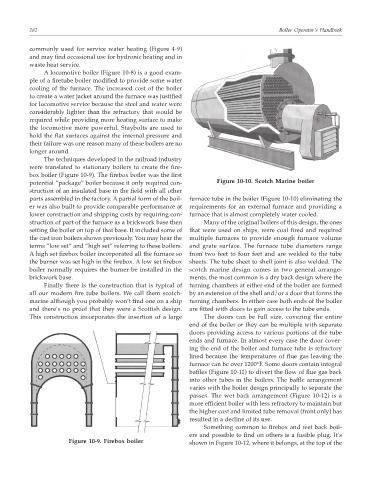
potential “package” boiler because it only required con- Figure 10-10. Scotch Marine boiler
struction of an insulated base in the field with all other
parts assembled in the factory. A partial form of the boil- furnace tube in the boiler (Figure 10-10) eliminating the
er was also built to provide comparable performance at requirements for an external furnace and providing a
lower construction and shipping costs by requiring con- furnace that is almost completely water cooled.
struction of part of the furnace as a brickwork base then Many of the original boilers of this design, the ones
setting the boiler on top of that base. It included some of that were used on ships, were coal fired and required
the cast iron boilers shown previously. You may hear the multiple furnaces to provide enough furnace volume
terms “low set” and “high set” referring to these boilers. and grate surface. The furnace tube diameters range
A high set firebox boiler incorporated all the furnace so from two feet to four feet and are welded to the tube
the burner was set high in the firebox. A low set firebox sheets. The tube sheet to shell joint is also welded. The
boiler normally requires the burner be installed in the scotch marine design comes in two general arrange-
brickwork base. ments, the most common is a dry back design where the
Finally there is the construction that is typical of turning chambers at either end of the boiler are formed
all our modern fire tube boilers. We call them scotch- by an extension of the shell and/or a door that forms the
marine although you probably won’t find one on a ship turning chambers. In either case both ends of the boiler
and there’s no proof that they were a Scottish design. are fitted with doors to gain access to the tube ends.
This construction incorporates the insertion of a large The doors can be full size, covering the entire
end of the boiler or they can be multiple with separate
doors providing access to various portions of the tube
ends and furnace. In almost every case the door cover-
ing the end of the boiler and furnace tube is refractory
lined because the temperatures of flue gas leaving the
furnace can be over 1200°F. Some doors contain integral
baffles (Figure 10-11) to divert the flow of flue gas back
into other tubes in the boilers. The baffle arrangement
varies with the boiler design principally to separate the
passes. The wet back arrangement (Figure 10-12) is a
more efficient boiler with less refractory to maintain but
the higher cost and limited tube removal (front only) has
resulted in a decline of its use.
Something common to firebox and wet back boil-
ers and possible to find on others is a fusible plug. It’s
Figure 10-9. Firebox boiler shown in Figure 10-12, where it belongs, at the top of the