
Page 296 - Boiler_Operators_Handbook,_Second_Edition
P. 296
Plants and Equipment 281
doesn’t mean a firetube boiler can’t be larger, I saw a is typically a brick walled enclosure constructed below
1400 horsepower firetube boiler a couple of years ago. the boiler. Many were built with the brick serving as a
It was a monster some ten feet in diameter and almost base to support the boiler. Few of those remain because
forty feet long; I would love to know how they kept the a furnace explosion which dislodges the bricks would
tubes in it from sagging. The lower cost of manufactur- result in the boiler collapsing into the furnace. More
ing firetube boilers has also increased the manufactur- modern HRT boilers are constructed with steel bases
er’s offering to 1,000 boiler horsepower. Sometimes they that support the boiler or a steel frame straddling the
do it by simply increasing the size of a burner on a 800 boiler and supporting it with suspension rods.
horsepower boiler. A constant problem with HRT boilers is mainte-
Firetube boilers come in several configurations and nance of protection for the bottom blowoff piping. In
arrangements. Basically they are cylindrical in shape many cases that pipe drops vertically through one end
(Figure 10-6) and are further defined by position and of the furnace and has to be protected by refractory be-
modifications to the general form. The arrangement in cause it would absorb so much heat that steam couldn’t
Figure 10-6 is typical of an HRT boiler (the letters stand escape it fast enough to allow water in. They go dry,
for Horizontal Return Tubular) which is an early design overheat, and rupture.
of boiler that has survived to modern times. Return in The other concern with HRT boilers is the bottom
the label indicates the flue gasses flow down some of where radiant heat from the furnace is absorbed by the
the boiler tubes from one end to the other then return shell. Any accumulation of mud in the bottom of the
through the remaining tubes. boiler tends to prevent cooling of the shell with resul-
A cross section is shown in the middle of the figure tant failure. The only service one of these boilers is pur-
that shows the tubes, how they’re arranged to permit the chased for today is in firing solid fuel, normally small
baffle at the rear and location of an access door for scrap- biomass applications because those applications require
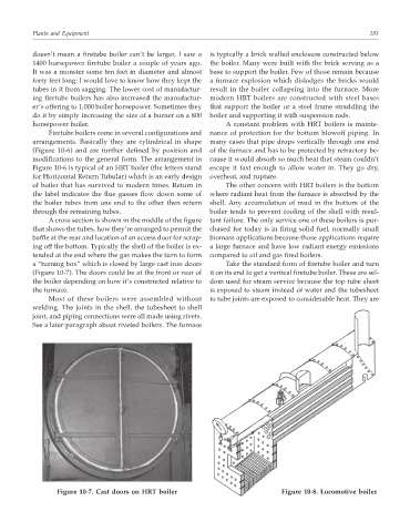
ing off the bottom. Typically the shell of the boiler is ex- a large furnace and have low radiant energy emissions
tended at the end where the gas makes the turn to form compared to oil and gas fired boilers.
a “turning box” which is closed by large cast iron doors Take the standard form of firetube boiler and turn
(Figure 10-7). The doors could be at the front or rear of it on its end to get a vertical firetube boiler. These are sel-
the boiler depending on how it’s constructed relative to dom used for steam service because the top tube sheet
the furnace. is exposed to steam instead of water and the tubesheet
Most of these boilers were assembled without to tube joints are exposed to considerable heat. They are
welding. The joints in the shell, the tubesheet to shell
joint, and piping connections were all made using rivets.
See a later paragraph about riveted boilers. The furnace
Figure 10-7. Cast doors on HRT boiler Figure 10-8. Locomotive boiler