
Page 309 - Boiler_Operators_Handbook,_Second_Edition
P. 309
294 Boiler Operator’s Handbook
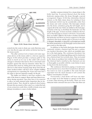
Another common internal for a steam drum is the
boiler feed line. To prevent thermal shock the boiler
feedwater piping enters the drum through a special
arrangement (Figure 10-30) that diminishes thermal
stresses on the thick steam drum by isolating it from
the feedwater (which may be considerably colder than
the steam and water mixture). The feed pipe extends
into the drum, sometimes going the full length, and is
capped off at the end. Holes are drilled in the feed pipe,
normally in the top, to distribute the feedwater over the
length of the pipe. At least one hole is drilled in the bot-
tom of the feed pipe to ensure it will drain. Occasionally
there are baffles added to the boiler to further distribute
the feedwater and there are always supports for the pipe
attached to the drum and the pipe to prevent it moving.
A flanged, threaded, or slip joint is provided just inside
the drum penetration so the feed pipe can be removed to
Figure 10-28. Steam drum internals
gain access to the tube ends.
In addition to that boiler feed pipe drum internals
extend into the water to drain any water that does carry
commonly include a chemical feed line and a continu-
over into the dry pipe and settles out before leaving via
ous (surface) blowdown line which are installed simi-
the steam nozzle.
lar to the feed piping. The continuous blowdown line
The other common form of steam and water sepa-
doesn’t require the tempering fitting used for feedwater
ration device at the steam outlet is a chevron separator
but a chemical feed line normally does. They are located
(Figure 10-29) which provides a tortuous path for the
in the drum in positions best suited for their purpose.
steam to travel on its way to the outlet with several
The chemical feed is installed so the chemicals can mix
changes in direction that tend to throw entrained water
as thoroughly as possible with the water before it starts
droplets against the chevron elements where they ac-
its trip down the downcomers.
cumulate then drain by sliding down the surface of the
The continuous blowdown piping is located near
chevron to the bottom forming large drops that fall off.
the surface but not so close that it would draw off steam.
Some modern boilers will have more complex baffling
You want it as close as possible to the water that just
arrangements for separating the steam and water but a
separated from the steam because it will contain the
dry pipe or chevron separator usually do the job.
highest concentration of solids.
The baffles are bolted to steel bars welded to the
Occasionally a mud drum will have one inter-
side of the drum to support them and keep them in po-
nal, an angle set in the bottom to spread out the flow
sition during operation. Since they have to be removed
of water when blowing off the boiler. There are more
to allow for each internal boiler inspection they’re fre-
elaborate boiler internals but most of the time these are
quently broken. They should be replaced when broken
because the movement of the water is so violent the lack
of one connection could allow a baffle to break away and
disrupt circulation to cause a boiler failure.
Figure 10-30. Feedwater line entrance
Figure 10-29. Chevron separator