
Page 306 - Boiler_Operators_Handbook,_Second_Edition
P. 306
Plants and Equipment 291
but I do know a lot were field erected. During my time flue gas to an up and down flow path to introduce ad-
with Power and Combustion I think we field erected ditional passes, usually making them a four pass design
half of the package boilers we installed. when the switching of directions is accounted for. The
The boiler in Figure 10-22 has tangent tube walls boilers without baffling have higher velocities through
at the side of the furnace, side of the convection bank, the screen tubes and the initial portion of the convection
and the baffle wall between the furnace and convection bank with attendant higher pressure drop on the gas
bank (except for the short section of screen tubes). Other side and higher furnace pressures to provide a balance
manufacturers provide finned tube walls (Figure 10- of heat transfer comparable to a multi-pass boiler.
23) where bars are welded between the tubes to form a Notice that I said most water tube boilers require
heat absorbing fin and eliminate the special bending of drums or headers, a boiler that consists of continuous
alternate tubes near the drum which is required to get a
tangent tube wall.
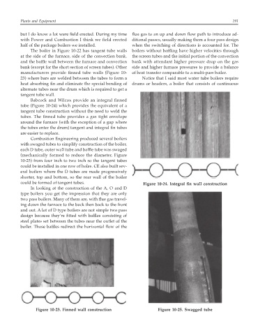
Babcock and Wilcox provide an integral finned
tube (Figure 10-24) which provides the equivalent of a
tangent tube construction without the need to weld the
tubes. The finned tube provides a gas tight envelope
around the furnace (with the exception of a gap where
the tubes enter the drum) tangent and integral fin tubes
are easier to replace.
Combustion Engineering produced several boilers
with swaged tubes to simplify construction of the boiler,
each D tube, outer wall tube and baffle tube was swaged
(mechanically formed to reduce the diameter, Figure
10-25) from four inch to two inch so the tangent tubes
could be installed in one row of holes. CE also built sev-
eral boilers where the D tubes are made progressively
shorter, top and bottom, so the rear wall of the boiler
could be formed of tangent tubes. Figure 10-24. Integral fin wall construction
In looking at the construction of the A, O and D
type boilers you get the impression that they are only
two pass boilers. Many of them are, with flue gas travel-
ing down the furnace to the back then back to the front
and out. A lot of D type boilers are not simple two pass
design because they’re fitted with baffles consisting of
steel plates set between the tubes near the outlet of the
boiler. Those baffles redirect the horizontal flow of the
Figure 10-23. Finned wall construction Figure 10-25. Swagged tube